
Laser projection with object feature detection

a technology of object feature detection and laser projection, applied in the field of laser projection systems, can solve the problems of reducing precision and reliability, time and labor consumption, and prior attempts to solve this problem have not provided a solution

Active Publication Date: 2007-12-11
FARO TECH INC
View PDF32 Cites 81 Cited by
  • Summary
  • Abstract
  • Description
  • Claims
  • Application Information

AI Technical Summary

Benefits of technology

The present invention is a laser projector system with feature detection and precision placement of component parts in 3D space. It uses a high-sensitivity optical feedback from a scanned object to separate the output beam and optical feedback beam, while suppressing unwanted background light. The system converts the optical feedback scan signal from the object's features into a digital image and defines the projector's location and orientation in 3D space with respect to the object's coordinate system. It can scan different object features, such as corners, holes, or other fabricated features, and obtain spatial coordinates of those features with respect to the projector's coordinate system prior to performing actual projection. The system also includes a method of generating a glowing template on an object for precision placement of component parts in 3D space, and a method of assembly a structure in 3D space with verification of the placement of component assembled parts and fabrication process steps on the object.

Problems solved by technology

The requirement to place reference targets onto the object has many practical drawbacks to the process of using laser projectors.
It is time and labor consuming.
It also degrades precision and reliability due to a lack of precision in the placement and resultant position of the target Some potentially viable applications currently cannot be implemented because they do not allow any target placement on the object surface.
However, prior attempts to solve this problem have not provided a solution without other drawbacks.
A serious drawback of the Rueb arrangement is the existence of two different optical paths for laser projection and camera imaging, which necessitates for frequent mutual calibration between the camera imaging system and the laser projection system.
As a result, the suggested solution reduced accuracy.
This unwanted “stray” light renders the optical feedback signal undistinguishable.
To date, no prior art laser projector that has been able to overcome this problem, that is, to distinguish very weak optical feedback signal in the presence of the powerful output projection beam and ambient light.
Human errors adversely impact any manufacturing process, they are unacceptable, and they have to be revealed as soon as possible.

Method used


Image

  • Laser projection with object feature detection
  • Laser projection with object feature detection
  • Laser projection with object feature detection

Examples


Embodiment Construction

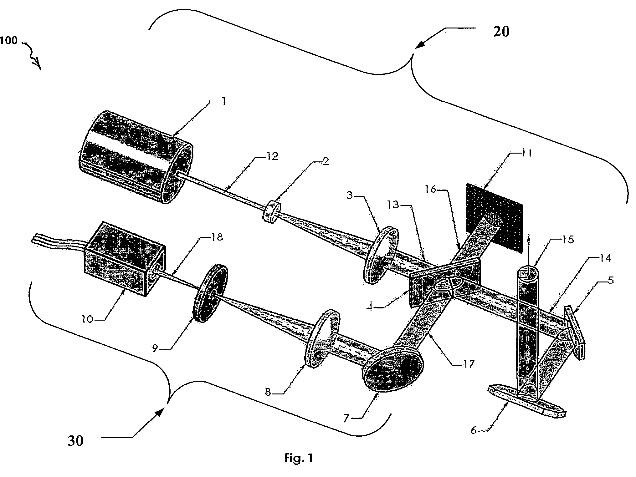
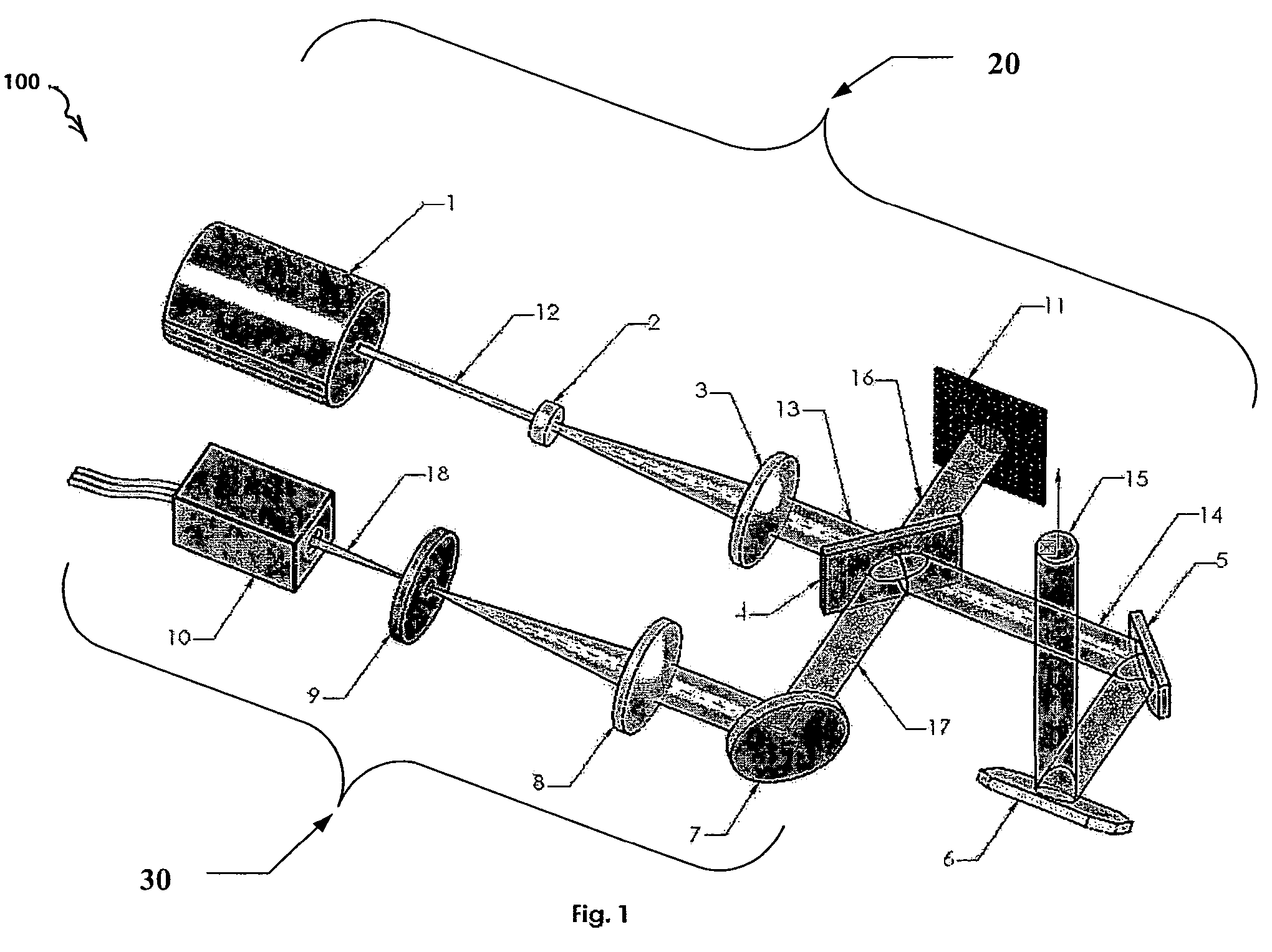
[0043]FIG. 1 shows a targetless laser projector (“TLP”) 20 according to the present invention. The TLP 20 has two major optical subsystems—a projection subsystem 20 and an optical feedback subsystem 30. The projection subsystem 20 includes a laser 1, beam expanding lenses 2 and 3, a beam splitter 4, a beam dump 11, and beam steering mirrors 5 and 6. The beam steering mirrors are mounted on shafts of corresponding galvanometers 203, 204 in FIG. 6, as is well known in the laser projection art. The optical feedback subsystem 30 includes a mirror 7, a focusing lens 8, a spatial filter 9, and a high-sensitivity photo detector 10.

[0044]The laser 1 emits a laser beam 12. The laser 1 is typically a solid state diode pumped laser that produces light at the “green” wavelength of 532 nanometers. The power of the beam 12 output by the laser is preferably not more than 5 milliwatts, the upper power limit for class IIIa lasers, and is a continuous wave output. The beam 12 has a typical diameter o...


PUM


Abstract

A laser projection system scans an output laser light beam onto an object to detect features. A high-sensitivity optical feedback system receives and detects a feedback beam of the output beam light diffusely reflected from the object. The feedback light and projected output beam share the same beam path between beam-steering mirrors of the projector and the object. The laser projection system has light suppression components to control stray scattered light, including ambient light, from being detected. A computer of the laser projection system calculates fiducial points on the object from detected features to align the projection system with the object without using targets. This feature detection is used in a process to guide assembly and fabrication on or to the object, and to verify the accurate placement of parts and fabrication steps in place after they are assembled or processed. In one form, the detected feature is a light spot on the object produced by a second light source.

Description

CROSS-REFERENCE TO RELATED APPLICATIONS[0001]This application claims priority under 35 USC 119(e) of U.S. Provisional Patent Application No. 60 / 649,241 filed on Feb. 1, 2005, the disclosure of which is incorporated herein by reference.FIELD OF THE INVENTION[0002]This invention relates to laser projection systems, and in particular to a laser projection system that projects a glowing template light pattern on an object without requiring retro-reflective or cooperative targets. This invention also relates to a targetless method of producing a glowing template to guide assembly, and a targetless method of assembly to verify the locations of parts after they are assembled or of other fabrication steps.BACKGROUND OF THE INVENTION[0003]Laser projectors are widely used in manufacturing processes to assist in precision assembly of large scale structures, composite articles, etc. in aerospace, construction and other industries. Laser projectors are distinguished from digitizing scanners. U.S...

Claims


Application Information

Patent Timeline
Patent Type & Authority Patents(United States)
IPC IPC(8): G01B11/03G01B11/14G03B21/26
CPCG01B11/2518G01N21/9515H04N9/3194G03B21/00G06T7/0057H04N9/3129H04N9/3185G01N21/4738G01N21/95623G01N2021/8411G01N2201/0642G01N2021/8472G06T7/521
Inventor KAUFMAN, STEVEN P.SAVIKOVSKY, ARKADYCHAGARIS, CHRISTOPHER C.STAVE, JOEL
Owner FARO TECH INC
Learn More