High energy fiber terminations and methods

a technology of high-energy fiber and termination, applied in the direction of optics, instruments, optical light guides, etc., can solve the problems of residual physical stresses and strains in traditional packages, degrade optical and mechanical affect the performance of the overall package, so as to achieve minimal physical stress, minimal physical distortion, and minimal physical distortion

Active Publication Date: 2007-12-18
BOSTON SCI SCIMED INC +1
View PDF7 Cites 4 Cited by
  • Summary
  • Abstract
  • Description
  • Claims
  • Application Information

AI Technical Summary

Benefits of technology

[0012]In the preferred embodiment, a ferrule wherein the constant diameter, axial bore is flared to a larger diameter at the end to be fused such that, upon fusing the fiber or capillary within the ferrule, contact angles in the weld region are high and the weld is centrosymmetric to the fused element and ferrule-to-single-strand fusion and is reproducibly short in length, physically centrosymmetric and low in stress.
[0024]To provide a generalized strategy and methodology for producing hermetic fusions in fiber, rod, capillary and tubing for minimization of residual stresses and uniformity in results.

Problems solved by technology

In most cases, adhesives secure components carried within ferrules but adhesives can be problematic in many applications due to the difference in chemical and physical properties of the adhesives with respect to the fiber and ferrule.
The stresses generated by thermal expansion mismatch can degrade optical and mechanical performance of the overall package.
Residual physical stresses and strains do remain in traditional packages, however, due to the extremely low contact angles in the fusion region.
As is generally known in the scientific glassblowing community, low contact angles in welds are extremely susceptible to failure due to these residual stress concentrations.
While post-fusion annealing can reduce the stresses in the weld, considerable stress generally remains and, in the case of fiber and capillary terminations, true post-fusion annealing is rarely possible due to the local presence of thermally labile materials (fiber and capillary polymer coatings, strain relief materials, etc.).
While generally successful in cases where fiber or capillaries are not doped or employ dopants that do not radically alter thermal properties of the glass or easily diffuse throughout the glass at elevated temperatures, attempts with doped core fiber such as that used in telecom / datacom applications and polymer clad fiber have had limited success.
Seals generally fail to hold, or the fiber and / or the ferrule fails, particularly when fiber and ferrule are of differing materials, coupling efficiencies are poor where core dopants diffuse under heating and where polymer clad fibers—necessarily bare of polymer near the fusion, leak into the ferrule at points of contact therein.
This distortion is primarily due to asymmetric, low contact angle stresses in the fusion seal and generally lengthy and poorly reproducible fusion regions.
It is extremely difficult to maintain uniformity of stresses and dimensions during a fusing operation and, due to the small diameter of both core and cladding (and in the case of polarization maintaining fibers, the precise stress distributions within the core composite structures), such difficulty renders the practice of fusion terminations for these type fibers impractical.
Even in cases where fusion has proven viable, e.g., so-called “Specialty Fiber” (fiber for power and spectrum transmission as opposed to data), fibers terminated within quartz and silica ferrules retain residual stress within the structure of the fiber and the ferrule, which may lead to premature failure.
Moreover, in the case of providing a preferentially softenable material as an interface between a telecom-type fiber and ferrule, asymmetric stresses due to low contact angles and non-centrosymmetric, extended fusion regions remain and the potential for premature failure continues to exist.

Method used


Image

  • High energy fiber terminations and methods
  • High energy fiber terminations and methods
  • High energy fiber terminations and methods

Examples


Embodiment Construction

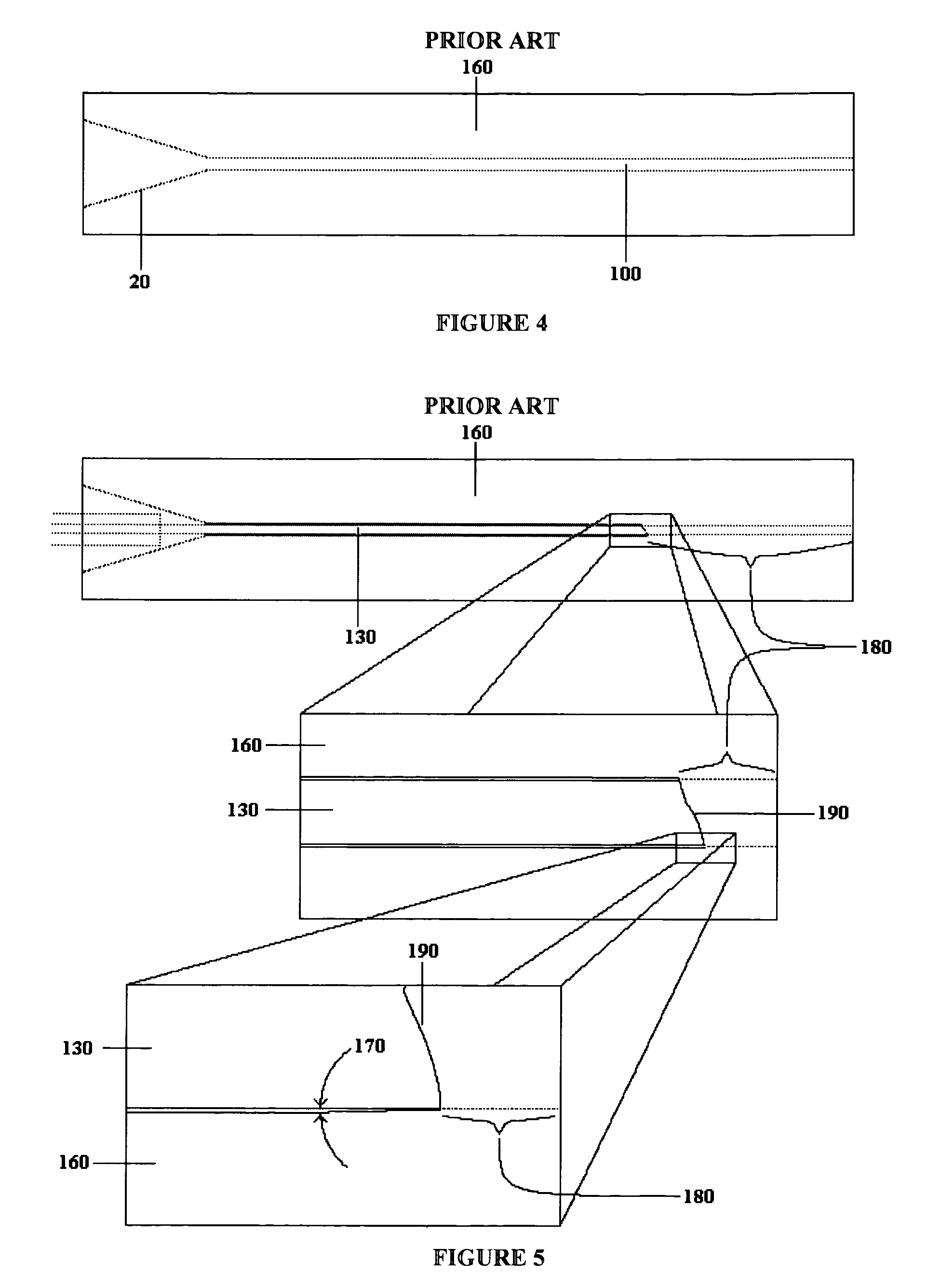
[0035]FIG. 4 comprises a view in section of the prior art ferrule 160, equipped with a standard insertion cone 20 to aid entry of delicate, bare fiber, which may or may not employ a preferentially softenable material within bore 110. A hermetic (fused) fiber-in-ferrule termination of prior art is illustrated in FIG. 5, comprising a view in partial section through the fused portion 180, illustrating the asymmetry 190 of the generally lengthy fusion with low contact angle 170 between the fiber 130 and ferrule 160.

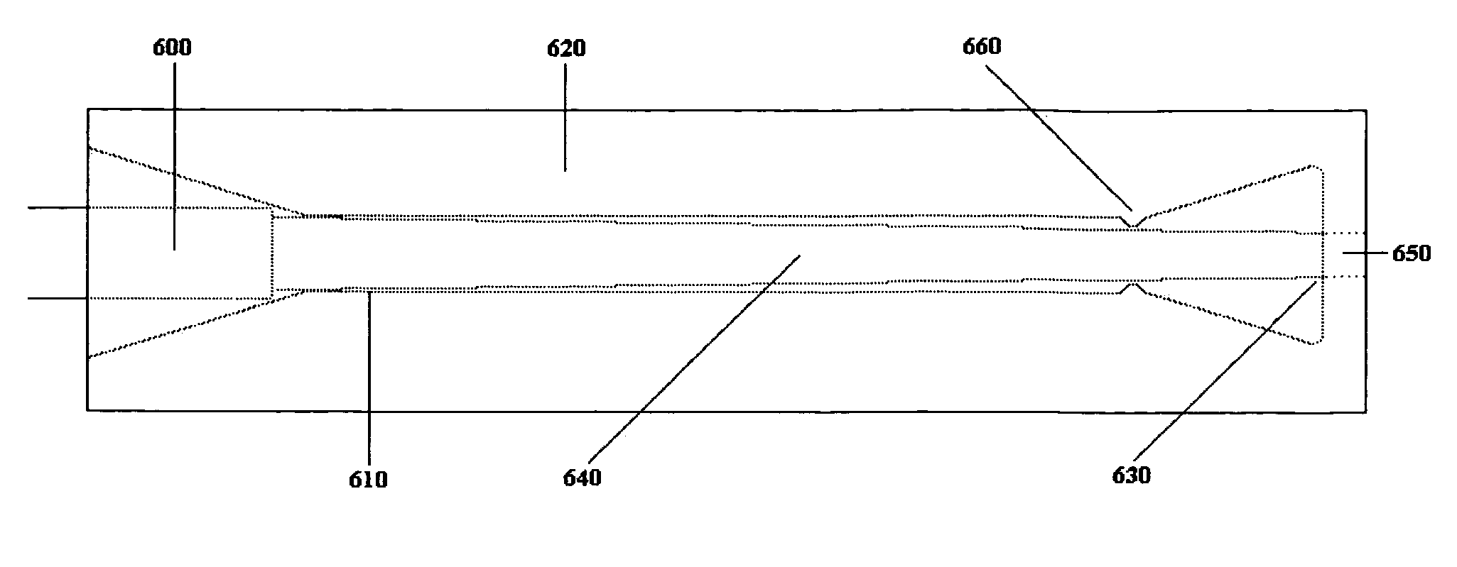
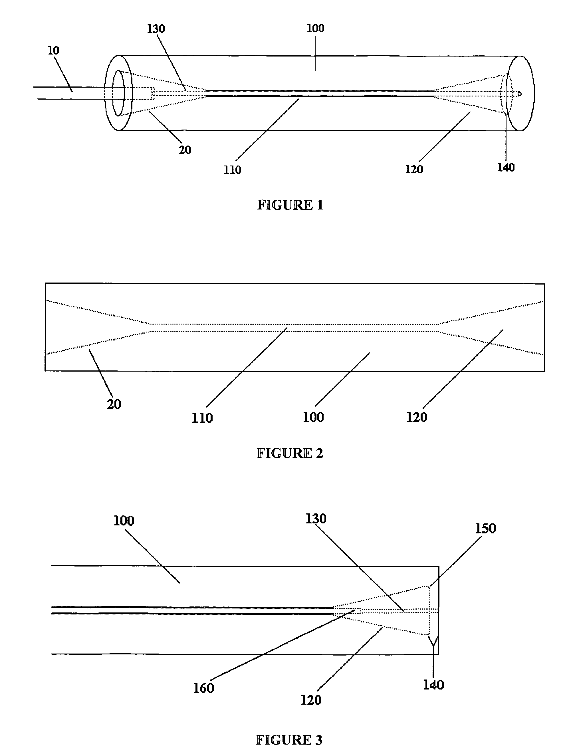
[0036]The preferred embodiment is illustrated in FIG. 1, comprising a perspective view of a fused, low stress termination of a buffered optical fiber 10 within the ferrule 100 with constant bore section 110 and terminal conical bores 120 and 20. The fragile, bare fiber section 130 is fused within one terminal conic bore 120 at 140. FIG. 3 is a view in partial section of the fusion portion of the terminated fiber-in-ferrule illustrating the relatively short, centrosymmetric fu...


PUM

PropertyMeasurementUnit
diameteraaaaaaaaaa
energyaaaaaaaaaa
softening temperatureaaaaaaaaaa

Abstract

A ferrule and method are presented that fuses optical fibers, capillaries and the like to ferrules while reducing deformation of the fused component and the ferrule and minimizing stresses within the assembly. Reduced deformation and stress is accomplished by providing high contact angles in a symmetrical, short section of fusion in fusing the component carried by the ferrule to the ferrule. It is particularly applicable to hermetic terminations of polymer clad fiber optics where irregular glass fusion joints cause irregular light leakage at the fiber launch but benefits are significant when used for other fiber and capillary architectures as well.

Description

FIELD OF THE INVENTION[0001]This invention relates generally to applications of silica core optical fiber in delivery of energy pulses or sustained power in surgery, welding and ordinance ignition as well as hermetic ferrule terminations of doped core fiber such as that used in telecommunications. The principles outlined herein may also apply to non-surgical applications, particularly where hermetic seals are desired in telecommunications and sensing applications of optical fiber for compliance with Telcordia standards, military specifications or other standards or in environments where hermetic seals are beneficial, e.g. “down hole” sensors for the oil industry.BACKGROUND OF THE INVENTION[0002]U.S. Pat. No. 4,185,883 (Chown et al.) discloses an optical fiber coupling element that includes a glass sleeve secured to a length of optical fiber. The optical fiber is placed in the glass sleeve, and the sleeve is heated so that it collapses around the fiber to hold the fiber in place.[000...

Claims


Application Information

Patent Timeline
Patent Type & Authority Patents(United States)
IPC IPC(8): G02B6/36
CPCG02B6/3855G02B6/3835G02B6/3813G02B6/4296
Inventor STEPHEN, GRIFFIN
Owner BOSTON SCI SCIMED INC
Why Eureka
Try Eureka