Laser scanning confocal microscope with fibre bundle return

a laser scanning and confocal microscope technology, applied in the field of laser scanning confocal microscope with fibre bundle return, can solve the problem that fibres may not be fused between the ends of bundles, and achieve the effect of improving focal plane isolation and improving focal plane isolation

Active Publication Date: 2008-02-12
OPTISCAN
View PDF7 Cites 17 Cited by
  • Summary
  • Abstract
  • Description
  • Claims
  • Application Information

AI Technical Summary

Benefits of technology

[0010]Further, this condition that the fibre bundle maintains image orientation only relates to the two ends of the fibre bundle. Thus, while a fused fibre bundle may be employed in some applications, in other applications the fibres may not be fused between the ends of the bundle, as long as the ends preserve a sufficient ‘coherence’ (i.e. image orientation maintenance) for the bundle to function as an imaging bundle. This latter type of bundle also has the advantage of greater flexibility over its length.
[0015]Preferably said microscope or endoscope includes a further beam-splitter, optically reversed relative to said beam-splitter and located optically after said fibre bundle, to improve focal plane isolation.
[0016]Thus, in one embodiment, said beam-splitter comprises a simple or compound prism, and said microscope or endoscope includes a further prism, optically reversed relative to said prism and located optically after said fibre bundle, to improve focal plane isolation.

Problems solved by technology

Thus, while a fused fibre bundle may be employed in some applications, in other applications the fibres may not be fused between the ends of the bundle, as long as the ends preserve a sufficient ‘coherence’ (i.e. image orientation maintenance) for the bundle to function as an imaging bundle.

Method used


Image

  • Laser scanning confocal microscope with fibre bundle return
  • Laser scanning confocal microscope with fibre bundle return
  • Laser scanning confocal microscope with fibre bundle return

Examples


Embodiment Construction

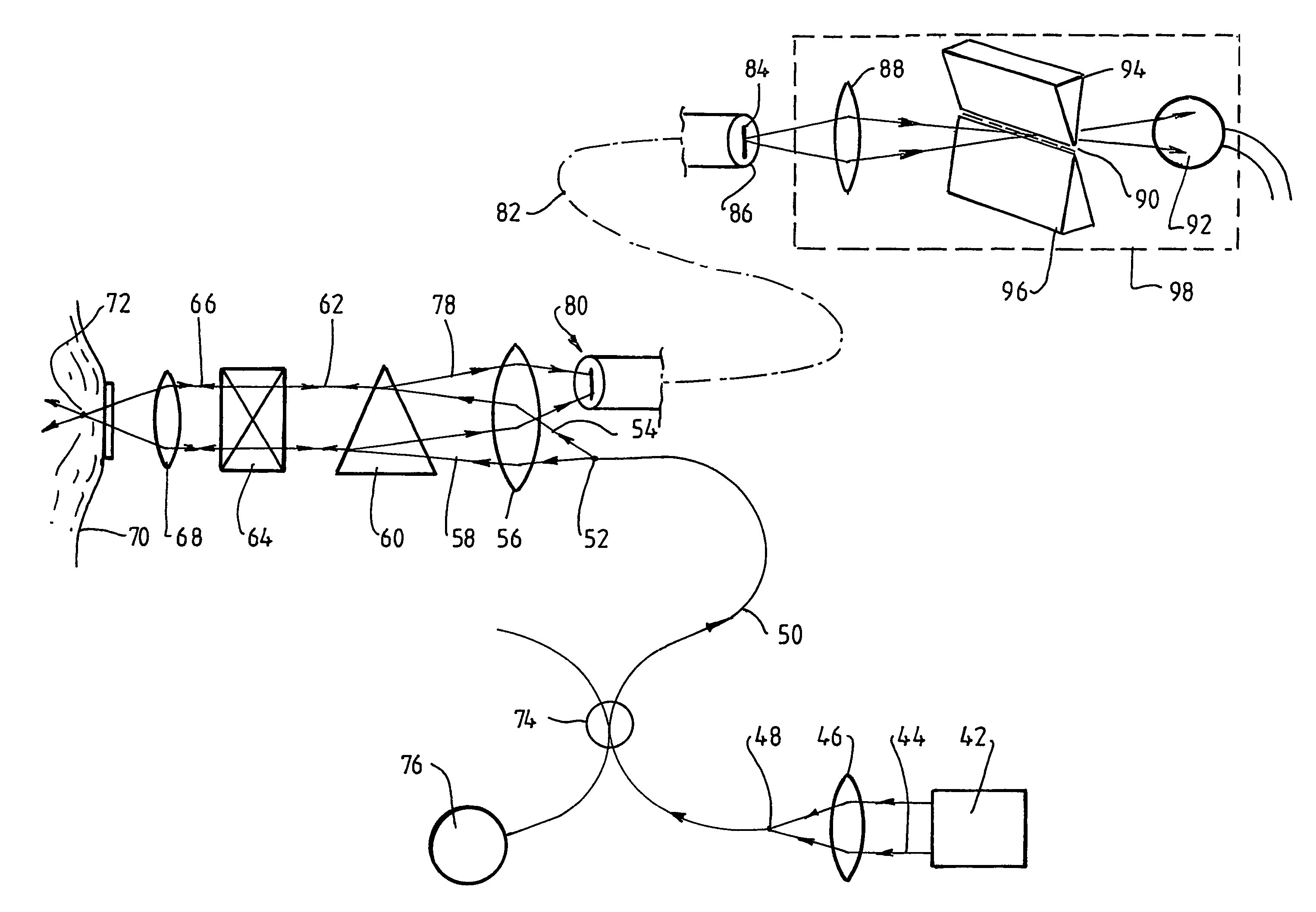
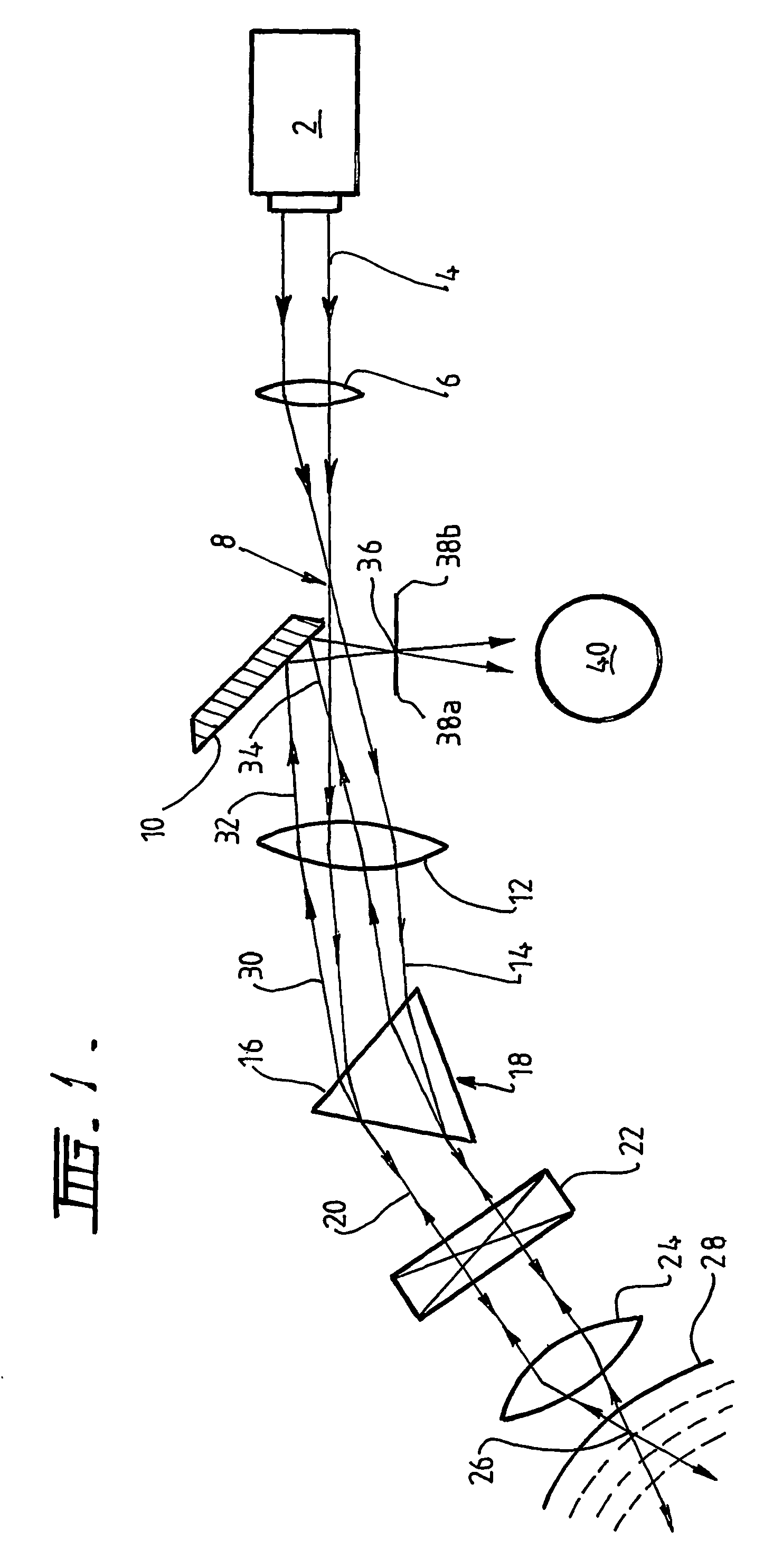
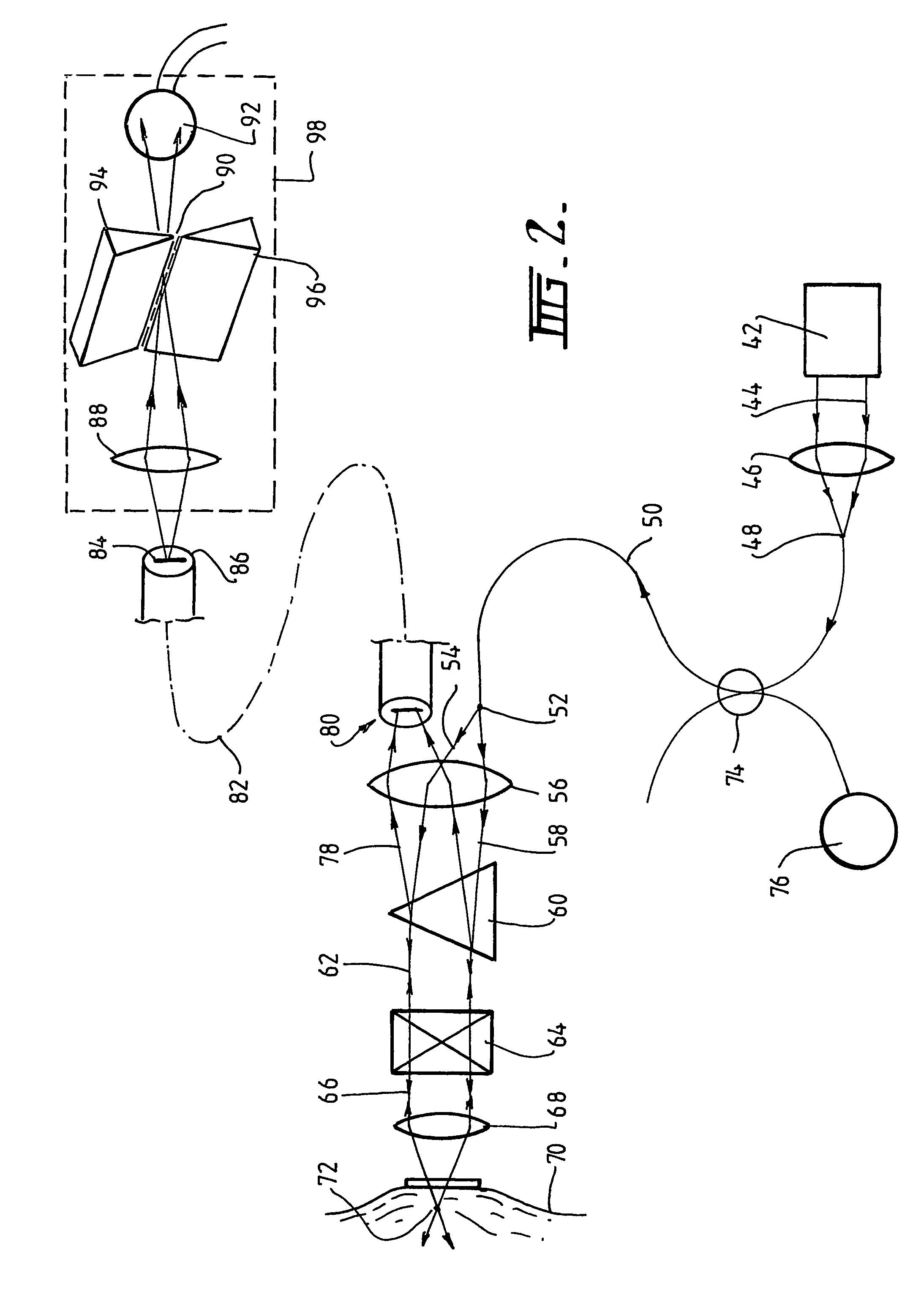
[0042]FIG. 1 illustrates how a prism can be used as a beam-splitter in an optical system suitable for a laser scanning confocal microscope in fluorescent imaging mode, though without—in this figure—embodying the present invention. A laser source 2 provides a laser beam 4, which is focussed by a lens 6 to a Gaussian waist 8 adjacent to the edge of a plane mirror 10. The light then diverges from this focus 8 until it meets a collimating lens 12, which collimates the beam 14 and projects it onto the face 16 of a glass prism 18.

[0043]The laser beam is TEMoo and monochromatic, and hence emerges from the prism 18 as a beam 20 with an unchanged parallel set of wave fronts. The beam passes through an XY scanner 22 and is focussed by a focussing lens 24 as diffraction limited spot 26 within the tissue sample 28. Fluorescence generated by the laser light in the tissue is Stokes shifted to longer wavelength than the wavelength of the excitation light from the laser. Fluorescent light from the ...


PUM


Abstract

The invention provides a confocal microscope or endoscope, having a source of coherent light for illuminating a sample, and an imaging optical fibre bundle (82) for receiving return light, whereby the fibre bundle (82) provides a return channel for fluorescent return light (78). The optical fibre bundle (82) preferably preserves, between entry and exit ends of the bundle, the relative spatial coordinates of the cores of individual fibres constituting the bundle.

Description

FIELD OF THE INVENTION[0001]The present invention relates to a laser scanning confocal microscope with fibre bundle return, for, in particular, improving the optical performance of laser scanning confocal microscopes. The invention may also have application in the miniaturisation of confocal endomicroscopes, in devices such as well plate readers, DNA chip scanners, in remote spectroscopy and as an optical system for a laser scanning ophthalmoscope.BACKGROUND OF THE INVENTION[0002]Existing two fibre confocal microscopes and endoscopes typically require precise fibre positioning and alignment in the probe head to provide separation of the light path. Existing systems also commonly require an extended beam path or further beam compressor optics in the microscope or endoscope head to give variable pinhole capability.SUMMARY OF THE INVENTION[0003]The present invention provides a confocal microscope or endoscope, having:[0004]a source of coherent light for illumination of a sample;[0005]a...

Claims


Application Information

Patent Timeline
Patent Type & Authority Patents(United States)
IPC IPC(8): G02B21/00A61B3/12G02B6/04
CPCG02B21/0028G02B21/0076A61B3/1225G02B6/04
Inventor HARRIS, MARTIN
Owner OPTISCAN
Why Eureka
Try Eureka