

Drill bit arcuate-shaped inserts with cutting edges and method of manufacture
a technology of arcuate-shaped inserts and drill bits, which is applied in the field of earth-moving bits, can solve the problems of affecting the performance of the inserts, affecting the performance of the drill bits, and requiring considerable time, effort and expense, and achieves the effect of enhancing the inserts' resistan
- Summary
- Abstract
- Description
- Claims
- Application Information
AI Technical Summary
Benefits of technology
Problems solved by technology
Method used
Image

Examples
Embodiment Construction
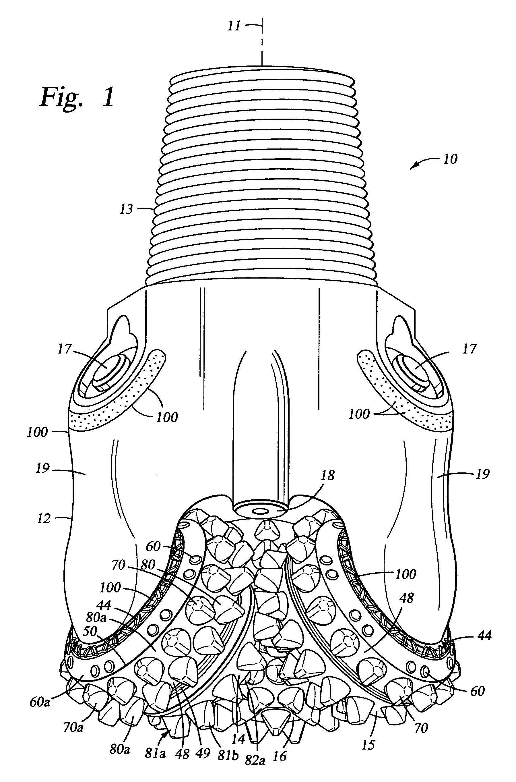
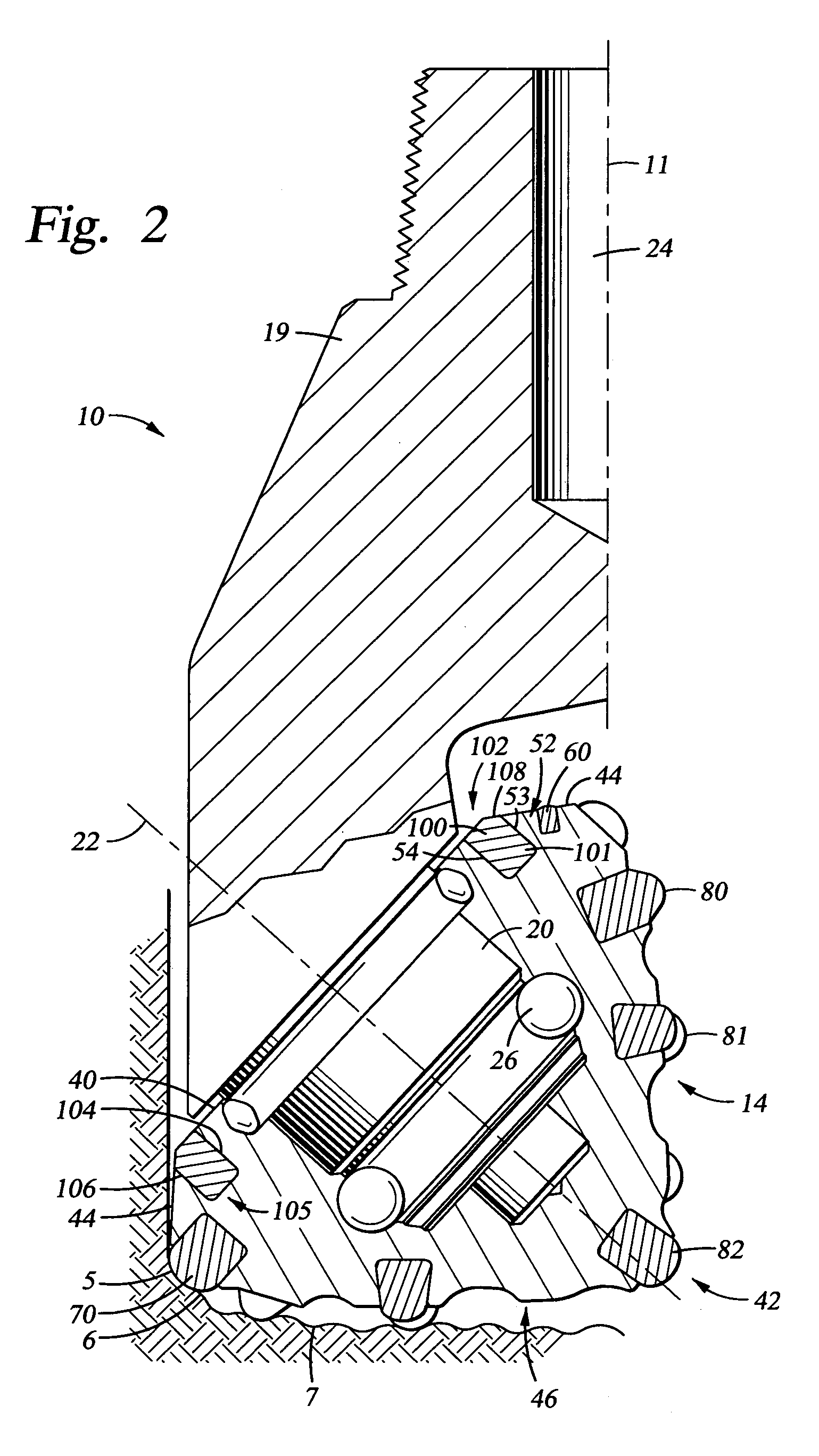
[0014]Preferred embodiments of the invention are disclosed that provide an earth boring bit having enhancements in cutter element design and in manufacturing techniques that provide the potential for increased bit life and footage drilled at full gage, as compared with similar bits of conventional technology. The embodiments disclosed include arcuate-shaped inserts of various arcuate lengths made through a conventional manufacturing process such as HIP. These inserts are disposed within a groove formed in the cone cutter of the rolling cone bit. Such inserts may also be placed in grooves formed elsewhere on the bit.
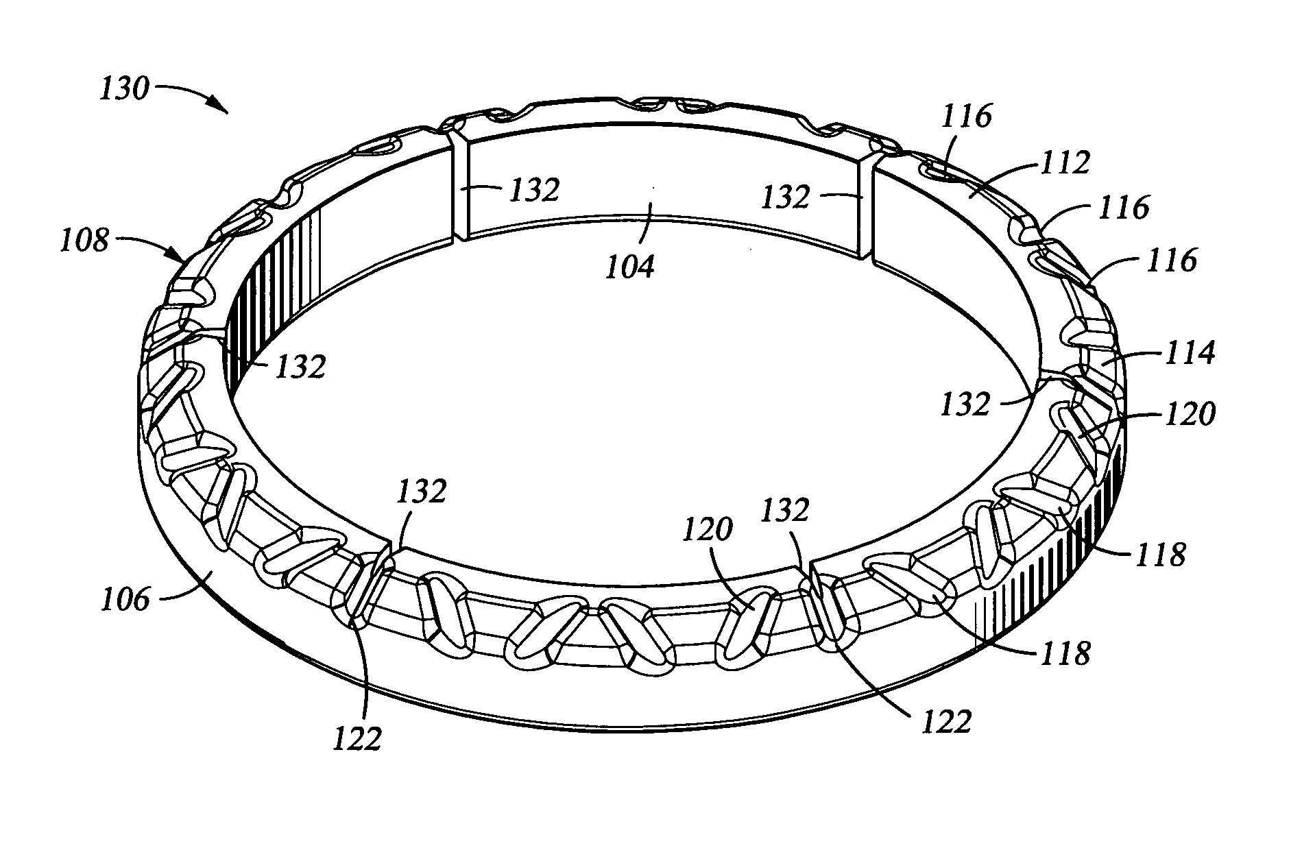
[0015]In certain embodiments, the arcuate-shaped inserts are disposed in an end-to-end relationship within the groove in the cone and substantially fill the cone groove. In other embodiments, the insert is a ring-shaped insert having a 360° arcuate length. In one aspect of the invention, inserts having 360° arcuate length are retained in a cone groove by interference fit,...
PUM
 Abstract
Description
Claims
Application Information