High voltage capacitors

a capacitor and high-voltage technology, applied in the field of high-voltage capacitors, can solve the problems of significantly affecting the properties of exposed electrodes, reducing the effective overlap area, so as to minimize the occurrence of unwanted disruptions, high capacitance, and high voltage breakdown in air

Active Publication Date: 2008-02-26
VISHAY SPRAGUE
View PDF13 Cites 37 Cited by
  • Summary
  • Abstract
  • Description
  • Claims
  • Application Information

AI Technical Summary

Benefits of technology

[0011]Therefore, it is a primary object, feature, or advantage of the present invention to improve upon the state of the art.
[0012]It is a further object, feature, or advantage of the present invention to provide a multilayer ceramic capacitor which is resistant to arc-over.
[0013]It is a still further object, feature, or advantage of the present invention to provide a multilayer ceramic capacitor with high voltage breakdown in air.
[0014]A still further object, feature, or advantage of the present invention is to provide a multilayer ceramic capacitor with a design which retains high capacitance.
[0015]Another object, feature, or advantage of the present invention is to minimize the occurrence of unwanted disruptions due to arc-over when the capacitor is incorporated into an electronic circuit.
[0016]Yet another object, feature, or advantage of the present invention is to provide a capacitor with high voltage withstanding capability with a smaller case size allowing for miniaturization of circuits.

Problems solved by technology

It is possible to further separate the floating electrode to give more than one floating electrode per layer to reduce the internal voltage but this also lowers the effective overlap area reducing capacitance.
However, it is important to note that exposed electrodes are subject to corrosion.
Also the properties of exposed electrodes are significantly impacted by the environment factors, such as humidity, limiting the applications in which these capacitors can be used.
In this case significant costs are associated with coating of the capacitors.
Furthermore, the coating may not be compatible with the circuit board assembly processes and the presence of organic coatings in some electronic application such as satellites is limited because of out gassing concerns.
Thus, despite various efforts to reduce produce capacitors with high voltage breakdown and which minimize occurrence of arc over, problems remain.

Method used


Image

  • High voltage capacitors
  • High voltage capacitors
  • High voltage capacitors

Examples


example 1

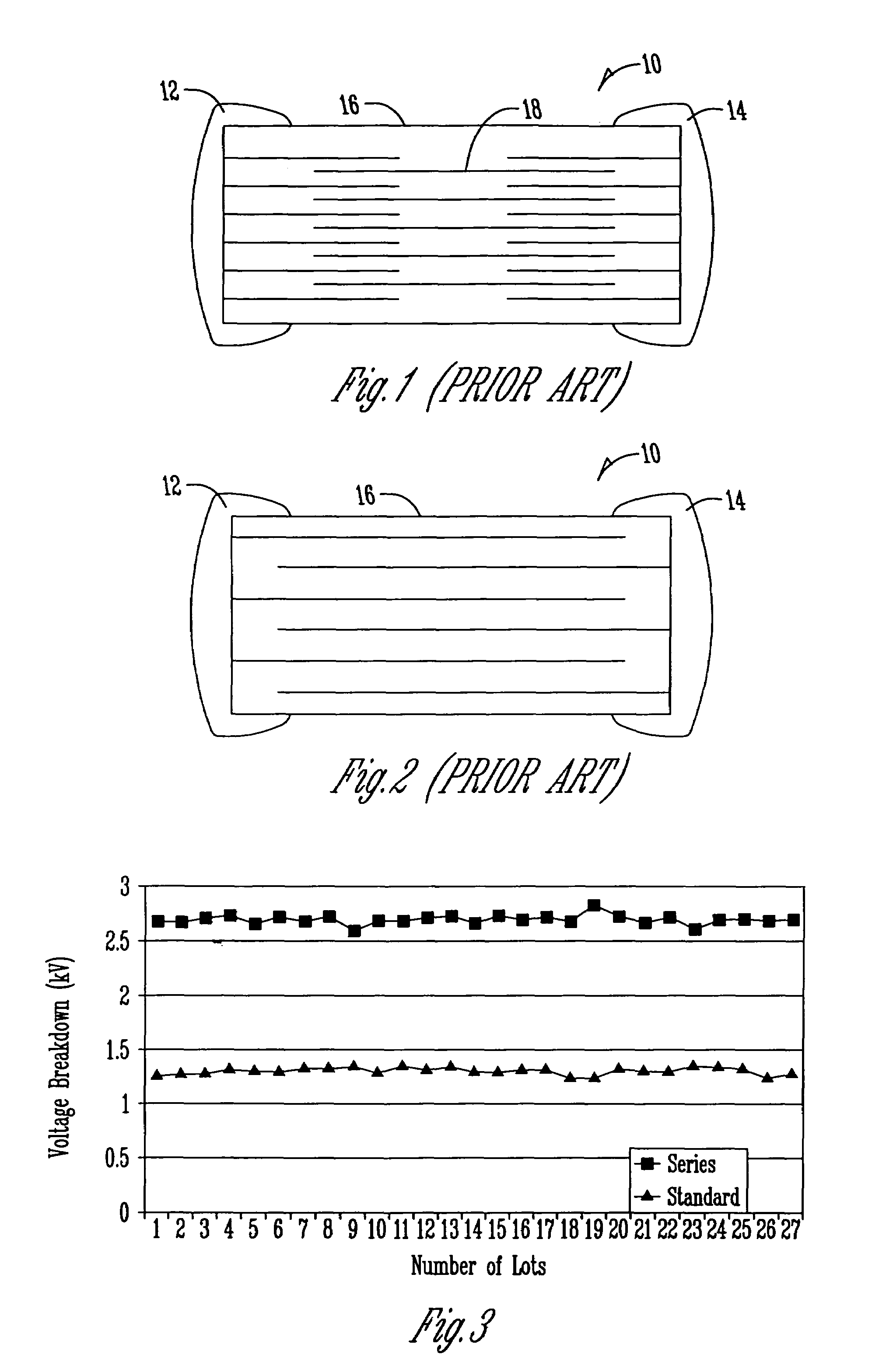
[0045]A standard case size 1206 capacitor design was manufactured using a production MLCC X7R materials system C-153.

example 2

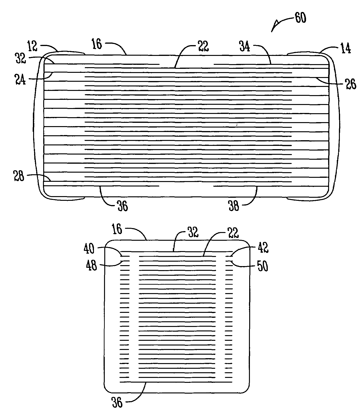
[0046]A case size 1206 capacitor design was manufactured using a production MLCC X7R materials system C-153 with shield electrodes on top and bottom. The purpose of these shield electrodes is to prevent an arc-over between the terminal and the internal electrode of opposite polarity or across the top or bottom surface of the capacitor between terminals of opposite polarity. For this reason it is only necessary to have one shield electrode present in the case where the active below is of opposite polarity. However, during the course of manufacturing capacitors of different values by shielding both terminal areas at the top and bottom of the capacitor there is no need to change the screens for different numbers of electrodes improving manufacturability.

example 3

[0047]A case size 1206 capacitor design was manufactured using a production MLCC X7R materials system C-153 with side shield electrodes on either side of the active in additions to shield electrodes on top and bottom. The purpose of the side shield electrode is to prevent an arc-over between the terminal and different internal electrode layers of opposite polarity or across the sides of the capacitor between terminals of opposite polarity. As for the top and bottom side shield electrodes, two side shield electrodes on each side were used but it is only necessary to have one side shield electrode at the side of each layer with terminal of opposing polarity. The two side shield electrodes on each side allows to accurately check alignment of the electrode stack.

[0048]The design and electrode pattern for all three examples is shown in FIG. 6. Terminals were applied to these examples consisting of a thick film fired silver paste and these were then over plated with nickel followed by tin...


PUM

PropertyMeasurementUnit
voltage breakdownaaaaaaaaaa

Abstract

A capacitor includes a ceramic capacitor body having opposite ends and comprised of a plurality of electrode layers and dielectric layers and first and second external terminals attached to the ceramic capacitor body. The internal active electrodes within the ceramic capacitor body are configured in an alternating manner. Internal electrode shields within the ceramic capacitor body are used to assist in providing resistance to arc-over. The shields can include a top internal electrode shield and an opposite bottom internal electrode shield wherein the top internal electrode shield and the opposite bottom internal electrode shield are on opposite sides of the plurality of internal active electrodes and each internal electrode shield extends inwardly to or beyond a corresponding external terminal to thereby provide shielding. Side shields are used. The capacitor provides improved resistance to arc-over, high voltage breakdown in air, and allows for small case size.

Description

BACKGROUND OF THE INVENTION[0001]Multilayer ceramic capacitors generally have alternating layers of ceramic dielectric material and conductive electrodes. Various types of dielectric materials can be used and various types of physical configurations have been used. Capacitors for high voltage performance have been produced for many years using a “series design”. In the series design the charge is stored between the floating electrode and electrodes connected to the terminals on either side as shown for a single floating electrode designs in FIG. 1. This compares to a standard capacitor design shown in FIG. 2 in which the electrodes alternatively connect to different terminals and the charge is stored between these electrodes. The capacitance for these designs is given by:C=∈o∈rAN / TWhere C=Capacitance in F[0002]∈o=Permittivity of Free Space=8.854×10⁻¹²Fm−1 [0003]∈r=Permittivity of the Ceramic Material, a material dependent dimensionless constant[0004]A=Effective Overlap Area of Elect...

Claims


Application Information

Patent Timeline
Patent Type & Authority Patents(United States)
IPC IPC(8): H01G4/005H01G4/06
CPCH01G4/012H01G4/30H01G4/232Y10T29/435H01G4/06H01G4/12
Inventor BULTITUDE, JOHNJIANG, JOHNROGERS, JOHN
Owner VISHAY SPRAGUE
Why Eureka
Try Eureka