Thermoelectric, high-efficiency, water generating device

a technology of thermal energy and water generation device, applied in the direction of defrosting, heating type, separation process, etc., can solve the problems of difficult water acquisition and much to be desired water quality, and achieve the effect of safe and efficient extraction of potable water and maximizing the efficiency of dehumidification process

Inactive Publication Date: 2008-03-04
INFINITE WATER
View PDF5 Cites 89 Cited by
  • Summary
  • Abstract
  • Description
  • Claims
  • Application Information

AI Technical Summary

Benefits of technology

[0003]The present invention provides a potable water generator designed to produce potable water from the ambient air using new and existing thermoelectric, sensing, and computational technologies and other known devices in a unique combination that safely and efficiently extracts potable water from the ambient air in a wider range of temperature and humidity conditions than traditional refrigerant-based systems. This invention deals with maximizing the efficiency of the dehumidification process by uniquely utilizing the cooled air to cool the heat sink of the thermoelectric device, supplemented, as needed, with additional ambient air passed over the heat sink The invention also deals with controlling the air flow in relation to the incoming ambient air temperature and the temperature of the cold sink as it relates to the dew point.
[0004]This invention provides for unique duct means that diverts and utilizes the cooled processed air to further increase the efficiency of cooling the thermoelectric heat sink, thereby significantly increasing the efficiency of the device. This duct can be supplemented with additional ambient air to further cool the heat sink as may be required.
[0006]This invention provides a repetitive means to determine the existing dew point of the ambient air and a means to control the rate of ambient air flow over the cold sink, which allows maximum condensation of the existing water vapor, with the minimum amount of expended energy, and over a wider range of temperature and humidity extremes.

Problems solved by technology

Countless other situations exist where water is difficult to obtain or where the quality of available water leaves much to be desired.

Method used


Image

  • Thermoelectric, high-efficiency, water generating device
  • Thermoelectric, high-efficiency, water generating device
  • Thermoelectric, high-efficiency, water generating device

Examples


Embodiment Construction

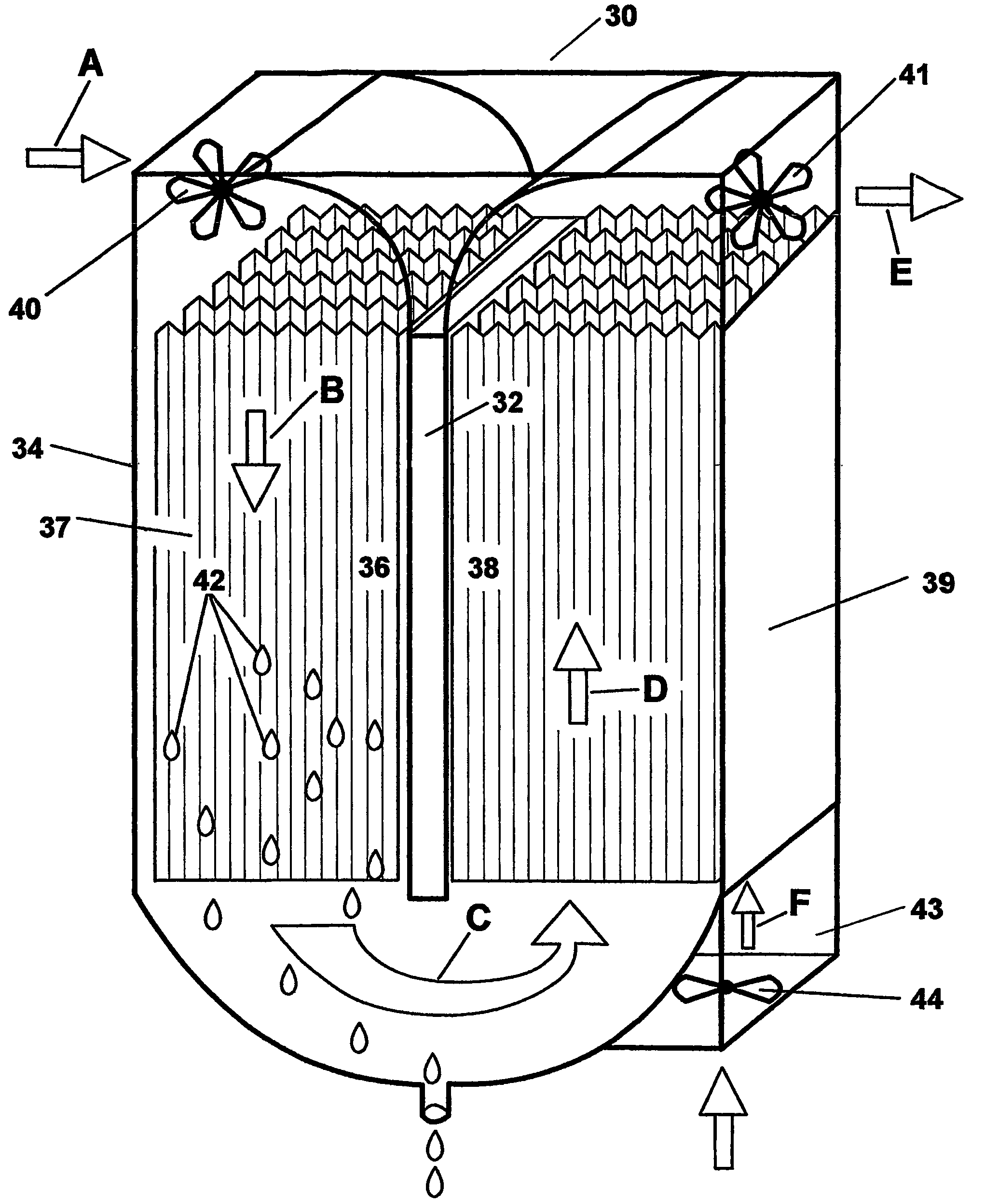
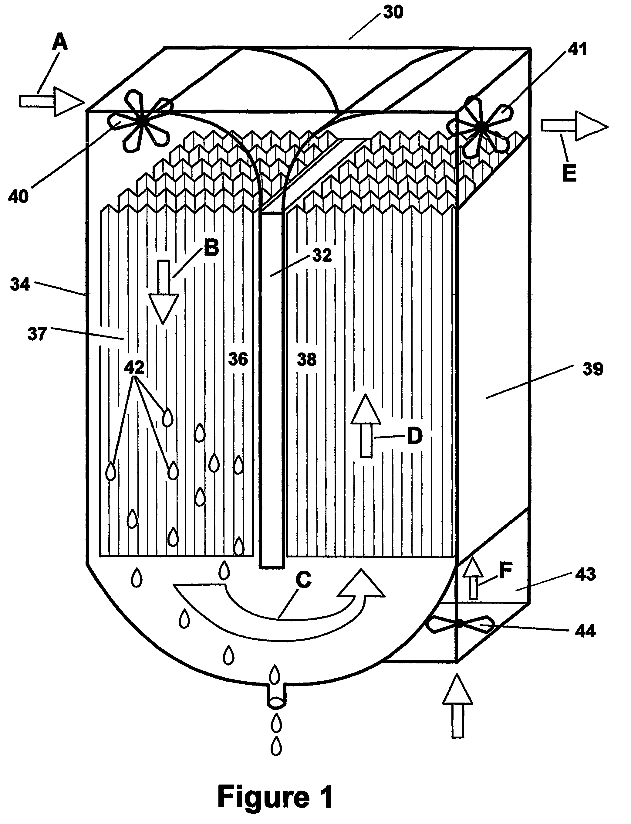
[0015]Water generating device 30 according to this invention, is shown in FIG. 1. Thermoelectric device 32 has cold sink 36 comprised of a number of cold sink fins 37 thermally coupled to the cold side of device 32, and heat sink 38 comprised of heat sink fins 39 thermally coupled to the hot side of device 32. Blower means 40 and / or 41 (such as fans) directs a stream of ambient air past cold sink 36 to cool the air below its dew point to condense water droplets 42 from the air. This also cools the air. Passage means 34, which may be an air duct, is arranged to direct the air cooled by cold sink 36 past heat sink 38. Since the air is cooled, more heat is drawn away from heat sink 38, which increases the efficiency of device 32, thus extracting or condensing more water from a given energy input. The air flow is depicted by arrows A, B, C, D, E and F. The water collection, treatment, storage, and delivery are not shown in this drawing for clarity purposes. A supplemental air flow of am...


PUM

PropertyMeasurementUnit
dew pointaaaaaaaaaa
speedaaaaaaaaaa
areaaaaaaaaaaa

Abstract

A water generating device utilizing thermoelectric cooling, also known as Peltier technology, for obtaining potable water from ambient air inside or outside a structure or dwelling, having a unique continuous duct for bringing this supply of ambient air to the device and for releasing the air back outside the device after it has been processed. This device includes a cold sink with which the incoming air is cooled below the dew point to condense the existing water vapor. The cooled air is then redirected over the heat sink which increases the efficiency and cooling capability of the device over that of using only the warmer ambient air to cool the heat sink. The rate of air flow is controlled by the variable speed of one or more fans or blowers. The fan or blower speed in turn is controlled by a device that determines the current ambient dew point by measuring the temperature and relative humidity, and the temperature of the cold sink. The incoming air flow is increased or decreased by the fan or blower, to the maximum possible flow rate without excessively exceeding the determined dew point temperature of the incoming air being processed.

Description

FIELD OF THE INVENTION[0001]The present invention relates to a water-condensing apparatus, and more particularly, to a thermoelectric device which makes potable water from the air.BACKGROUND OF THE INVENTION[0002]In recent years, it is becoming more useful for people in both offices and in the home to drink bottled water rather than water from a water tap. Countless other situations exist where water is difficult to obtain or where the quality of available water leaves much to be desired. In many cases this also creates a need to carry the water from the place where it was purchased to the place where it will be used. Accordingly, there have been some attempts to provide on-site water generation to alleviate these problems. Virtually all of these attempts have utilized more traditional methods of conventional compressors, refrigerant, and evaporator and condenser coils. Some attempts have been made to extract water vapor from the air using thermoelectric technology on a small scale,...

Claims


Application Information

Patent Timeline
Patent Type & Authority Patents(United States)
IPC IPC(8): F25B21/02B01D5/00B01D21/30B01D53/26C02FC02F1/00C02F1/18C02F1/32E03B3/28F24F3/153F25D21/14
CPCB01D5/0042B01D53/265E03B3/28F24F3/153F25B21/02C02F1/18C02F1/32F24F5/0042Y02W10/37Y02A20/00
Inventor REIDY, JAMES J.
Owner INFINITE WATER
Why Eureka
Try Eureka