Light source apparatus

a technology of light source and light source, applied in the direction of lasers, laser details, instruments, etc., to achieve the effect of suppressing the power reduction of pulsed ligh

Active Publication Date: 2008-03-04
SUMITOMO ELECTRIC IND LTD
View PDF8 Cites 8 Cited by
  • Summary
  • Abstract
  • Description
  • Claims
  • Application Information

AI Technical Summary

Benefits of technology

[0019]In the broadband light source described in Patent Document 1, as in the foregoing, pulsed light (generated pulsed light) in which the input pulsed light is compressed is produced in the region extending from the light entrance end of the DDF 1 to the distance L1, whereas broadband light is produced according to the generated pulsed light in the region extending from the distance L1 to L2. Therefore, when wavelength shifting conditions and SC conditions in the DDF 1 are appropriately designed and controlled, broadband light having a desirable wavelength band and bandwidth can be produced while minimizing the waste of energy.
[0023]For solving the problems mentioned above, it is an object of the present invention to provide a light source apparatus which stably supplies broadband pulsed light having a wavelength spectrum with an excellent flatness over a wide band by combining a short-pulsed light source having an excellent output pulse characteristic with a broadband light producing fiber which is favorably combinable with the short-pulsed light source.
[0027]The light source apparatus according to the present invention may further comprise a coupling fiber arranged between the pulsed light source and the broadband light producing fiber. The coupling fiber has a light entrance end (with a coupling loss of 3 dB or less, preferably 1 dB or less) and a light exit end fusion-spliced to the light entrance end of the broadband light producing fiber. When the coupling fiber is arranged in front of (on the upstream of) the broadband light producing fiber having a severe coupling condition, the coupling loss is reduced, whereby the resistance to fluctuations such as vibrations can be improved. The structure in which the light exit end of the coupling fiber and the light entrance end of the broadband light producing fiber are fusion-spliced to each other reduces the splice loss between the splice fiber and the broadband light producing fiber, whereby the seed light can be made incident on the broadband light producing fiber more efficiently. In particular, for raising the power of seed light incident on the broadband light producing fiber, an amplification fiber may be employed as the coupling fiber.
[0030]In the light source apparatus according to the present invention, the pulsed light source may be a fiber laser. When the output end of the pulsed light source is a light output end of an optical fiber member in particular, the light entrance end of the broadband light producing fiber can directly be fusion-spliced thereto without the aid of the coupling fiber mentioned above. This greatly suppresses the reduction in the power of pulsed light incident on the broadband light producing fiber.
[0031]For further raising the power of pulsed light incident on the broadband light producing fiber, it will be preferred if the fiber laser is partly constructed by an amplification fiber.
[0033]The pulsed light source may include an electrooptic modulator in order to make it possible for electric signals from the outside to regulate the pulsed light source itself. Preferred as the electrooptic modulator in this case are lithium niobate which is excellent in high-speed response and semiconductor optical amplifiers which can be made smaller and integrated.

Problems solved by technology

The inventors studied the conventional techniques mentioned above and, as a result, have found the following problems.

Method used


Image

  • Light source apparatus
  • Light source apparatus
  • Light source apparatus

Examples


first embodiment

[0054]FIG. 3 is a view showing the structure of a first embodiment of the light source apparatus according to the present invention.

[0055]As shown in the area (a) of FIG. 3, the light source apparatus 100 according to the first embodiment comprises a pulsed light source 110, an erbium-doped fiber amplifier (EDFA) 120, a highly nonlinear fiber (HNLF) 130 wound as a broadband light producing fiber about a coil, and bandpass filters BPFs 141, 142 arranged at both ends of the highly nonlinear fiber 130. For making it possible to connect with other optical components such as an optical fiber transmission line 300, a connector 150 is arranged at an output end of the light source apparatus 100. For directly regulating the output pulse characteristic of the pulsed light source 110, the light source apparatus 100 may further comprise a controller 160 as shown in the area (b) of FIG. 3.

[0056]The wavelength spectrum of the broadband pulsed light finally emitted from the light source apparatus ...

second embodiment

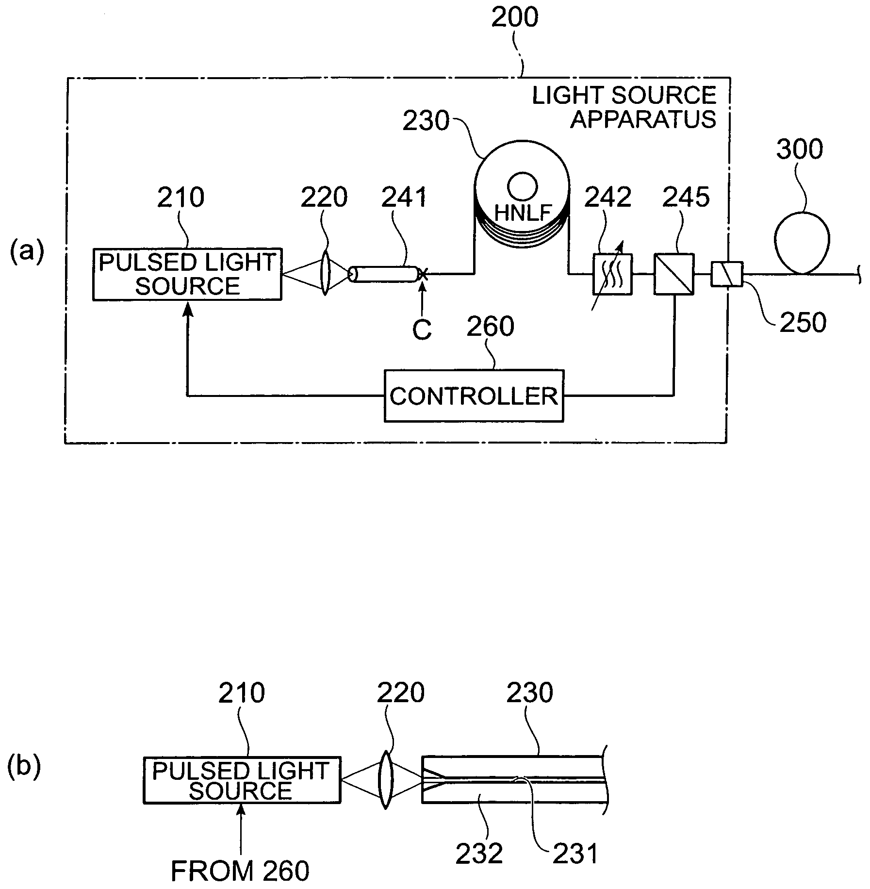
[0091]FIG. 15 is a view showing the structure of a second embodiment of the light source apparatus according to the present invention. The light source apparatus 200 according to the second embodiment includes a structure of feedback-controlling the power of broadband pulsed light emitted therefrom.

[0092]Namely, as shown in the area (a) of FIG. 15, the light source apparatus 200 comprises a pulsed light source 210, a lens 220, a coupling fiber 241, a highly nonlinear fiber (HNLF) 230 as a broadband light producing fiber, a bandpass filter 242, a demultiplexer 245, and a controller 260. At the output end of the light source apparatus 200, a connector 250 whose connecting part is obliquely cut is arranged in order to make it connectable with other optical components such as the optical fiber transmission line 300. The output pulse characteristic of the pulsed light source 210 is the same as that of the pulsed light source 110 in the first embodiment, whereas the optical characteristic...


PUM


Abstract

The present invention relates to a light source apparatus having a structure for stably supplying broadband pulsed light having a wavelength spectrum with an excellent flatness over a wide band. The light source apparatus employs, as a seed light source, a short-pulsed light source having such an excellent output pulse characteristic that the frequency bandwidth extending until the output pulse drops by 10 dB or 20 dB from a peak is 5 THz or more. The light source apparatus also includes a broadband light producing fiber having an optical characteristic suitable for combining with the short-pulsed light source. The broadband light producing fiber inputs pulsed light from the pulsed light source, and produces the broadband pulsed light by utilizing a nonlinear optical phenomenon. This structure yields broadband pulsed light having such a wavelength spectrum that a region whose power fluctuation is suppressed to 6 dB or less extends over 100 nm or more.

Description

CROSS-REFERENCE TO RELATED APPLICATION[0001]This application claims priority to Provisional Application Ser. No. 60 / 666,571 filed on Mar. 31, 2005 by the same Applicant, which is hereby incorporated by reference in its entirety.BACKGROUND OF THE INVENTION[0002]1. Field of the Invention[0003]The present invention relates to a light source apparatus which generates broadband light by utilizing a nonlinear optical phenomenon in an optical fiber.[0004]2. Related Background Art[0005]As optical communication techniques evolve, light sources generating short-pulsed light with a wide output band are expected. As a technique concerning such a light source, attention has been given to SC (supercontinuum) light which is broadband pulsed light generated when pulsed light having a high peak power is caused to enter an optically nonlinear medium as seed light. In particular, Patent Document 1 discloses a light source apparatus for generating SC light.[0006]Mainly known as seed light sources (puls...

Claims


Application Information

Patent Timeline
Patent Type & Authority Patents(United States)
IPC IPC(8): G02B6/00
CPCG02B6/03627G02B6/03644G02B6/03666H01S3/0057G02B6/02028G02B6/02285G02B6/29377H01S3/06725
Inventor OKUNO, TOSHIAKI
Owner SUMITOMO ELECTRIC IND LTD
Why Eureka
Try Eureka