Solid electrolytic capacitor

a solid electrolytic capacitor and capacitor technology, applied in the direction of liquid electrolytic capacitors, casings/cabinets/drawers, electrical equipment casings/cabinets/drawers, etc., can solve the problems of increased leakage current and short circuit, and achieve the effect of reducing esr, reducing esr, and high frequency rang

Active Publication Date: 2008-03-11
PANASONIC CORP
View PDF8 Cites 11 Cited by
  • Summary
  • Abstract
  • Description
  • Claims
  • Application Information

AI Technical Summary

Benefits of technology

[0012]The present invention provides a solid electrolytic capacitor with more reduced ESR in a high frequency range. The solid electrolytic capacitor of the present invention includes a plurality of capacitor elements, an anode portion, a conductive sheet, a cathode portion, an anode terminal, a cathode terminal and a packaging resin layer. The plurality of capacitor elements are laminated together and each includes an anode body, a dielectric oxide film, a solid electrolyte layer and a cathode layer. The anode body is made of a valve metal having an anode exposed portion. The dielectric oxide film is formed on the surface of the anode body. The solid electrolyte layer is formed on the surface of the dielectric oxide film. The cathode layer is formed on the surface of the solid electrolyte layer. In the anode portion, the anode exposed portions of the plurality of capacitor elements are bonded together. The conductive sheet is disposed between the lamination planes of the cathode layers of the plurality of capacitor elements. In the cathode portion, the cathode layers of the plurality of capacitor elements are bonded together via the conductive sheet. The anode terminal and the cathode terminal are connected to the anode portion and the cathode portion, respectively. The packaging resin layer coats the plurality of capacitor elements in such a manner as to expose a part of the anode terminal and a part of the cathode terminal. In this structure, little deformation of the conductive sheet causes so that the bonded area between the cathode layers can be stably secured, thereby reducing ESR without increasing leakage current. The conductive sheet can minimize the gas generation so as to allow the cathode layers and the conductive sheet to have few cavities on the interface. As a result, ESR is reduced.

Problems solved by technology

This leads to an increase in leakage current and may cause a short circuit.

Method used


Image

  • Solid electrolytic capacitor
  • Solid electrolytic capacitor
  • Solid electrolytic capacitor

Examples


first exemplary embodiment

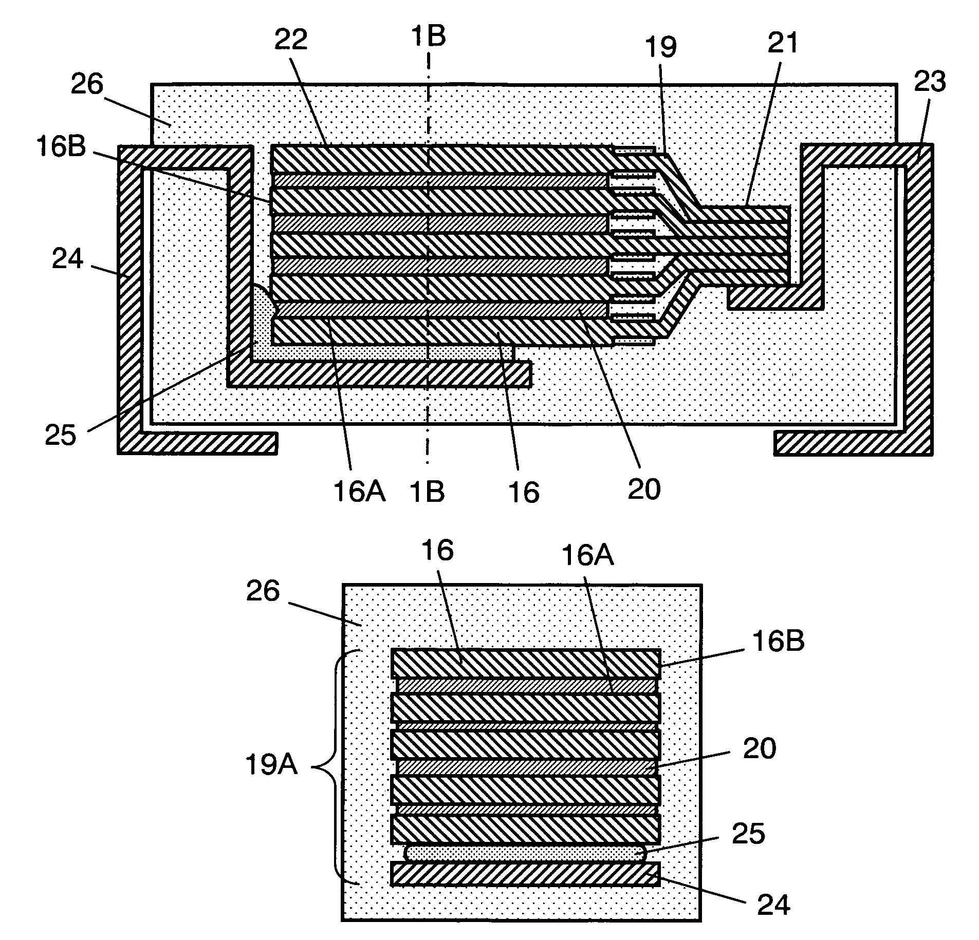
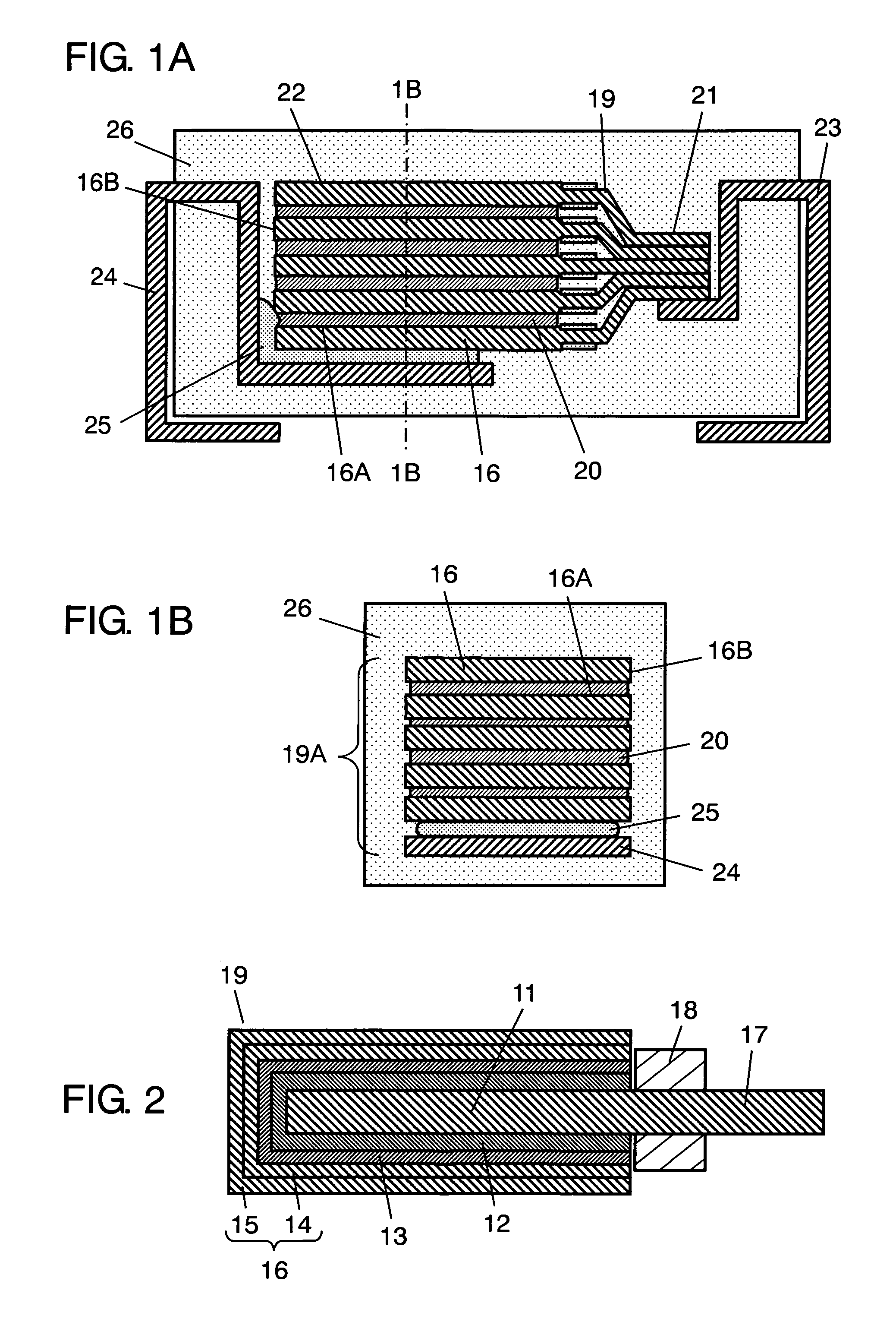
[0034]FIG. 1A is a front sectional view showing the structure of a solid electrolytic capacitor of a first exemplary embodiment of the present invention. FIG. 1B is a side sectional view of the solid electrolytic capacitor taken along the line 1B-1B of FIG. 1A. FIG. 2 is a sectional view showing the structure of a capacitor element of the solid electrolytic capacitor.

[0035]As shown in FIG. 2, capacitor element 19 includes anode body 11, insulating layer 18, dielectric oxide film 12, solid electrolyte layer 13 and cathode layer 16. Anode body 11 is a valve metal foil and includes anode exposed portion 17. Dielectric oxide film 12 is formed by anodization on the surface of the portion of anode body 11 that is divided from anode exposed portion 17 by insulating layer 18. The valve metal used for anode body 11 can be aluminum, tantalum, niobium, titanium or the like. Besides a valve metal foil, anode body 11 can be a porous sintered body made of valve metal powder.

[0036]Solid electrolyt...

second exemplary embodiment

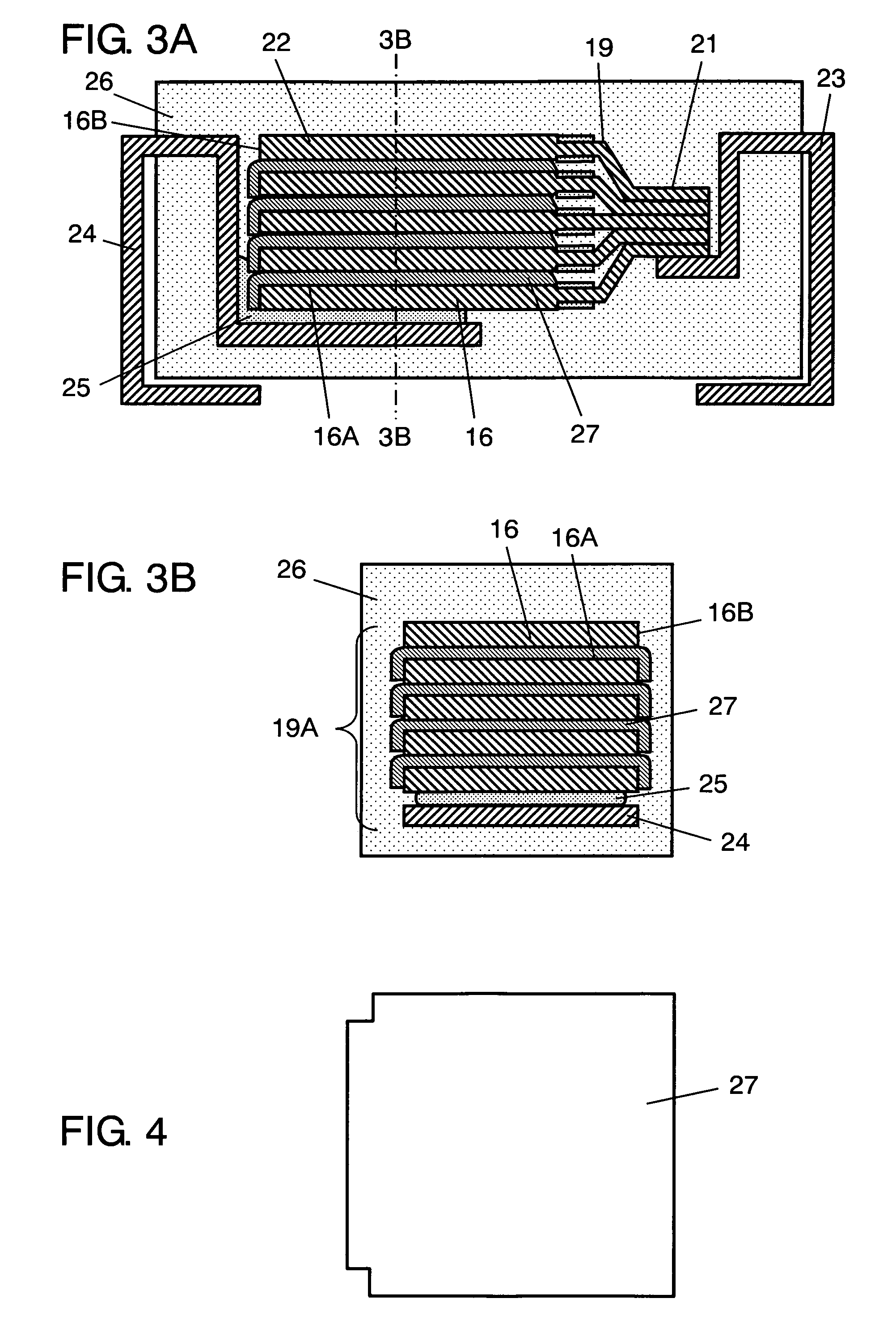
[0084]FIG. 14 is a sectional view showing the structure of a solid electrolytic capacitor of a second exemplary embodiment of the present invention. FIG. 15 is a plan view showing an arrangement between a conductive sheet having a penetrating portion and a conductive paste layer in the solid electrolytic capacitor shown in FIG. 14. In FIG. 15, the conductive sheet and the conductive paste are taken along a sectional plane at the line 15-15 of FIG. 14.

[0085]The solid electrolytic capacitor of the present embodiment differs from that of the first exemplary embodiment in that the conductive sheets are each provided with a penetrating portion, and the penetrating portion has a conductive paste layer formed therein. The other fundamental structure is identical to that of the first exemplary embodiment, so that it will not be described in detail again.

[0086]Conductive sheet 40 is made of the same materials as conductive sheet 20 used in the first exemplary embodiment. Conductive sheet 40 ...


PUM

PropertyMeasurementUnit
particle diameteraaaaaaaaaa
thicknessaaaaaaaaaa
particle diameteraaaaaaaaaa

Abstract

A solid electrolytic capacitor includes a plurality of laminated capacitor elements; an anode terminal connected to an anode portion where anode exposed portions of the capacitor elements are connected together; and a cathode terminal connected to a cathode portion where cathode layers of the capacitor elements are bonded together. Between lamination planes of the cathode layers of the capacitor elements, a conductive sheet is disposed. The capacitor elements are coated with a packaging resin layer in such a manner that a part of the anode terminal and a part of the cathode terminal are exposed.

Description

BACKGROUND OF THE INVENTION[0001]1. Field of the Invention[0002]The present invention relates to a solid electrolytic capacitor used in a variety of electronic devices.[0003]2. Background Art[0004]With the recent digitization of electronic devices, solid electrolytic capacitors used in these devices are increasingly demanded to reduce equivalent series resistance (hereinafter, referred to as ESR) in a high frequency range. The following is a description of the structure of a conventional solid electrolytic capacitor with reference to FIGS. 18 and 19. FIG. 18 is a sectional view showing the structure of the conventional solid electrolytic capacitor, and FIG. 19 is a sectional view showing the structure of a capacitor element of the solid electrolytic capacitor.[0005]As shown in FIG. 19, capacitor element 69 includes anode body 61, insulating layer 63, dielectric oxide film 64, solid electrolyte layer 65 and cathode layer 68. Anode body 61, which is planar, is made of a valve metal su...

Claims


Application Information

Patent Timeline
Patent Type & Authority Patents(United States)
IPC IPC(8): H01G9/00
CPCH01G9/012H01G9/06H01G9/26H01G9/14Y10T29/41Y10T29/417
Inventor TADANOBU, KAZUOYAMAGUCHI, HIDETONISHIDA, KAZUYO
Owner PANASONIC CORP
Why Eureka
Try Eureka