Harmonic pulse laser apparatus, and method for generating harmonic pulse laser beams

a laser beam and harmonic pulse technology, applied in the direction of instruments, knitting, active medium materials, etc., can solve the problems of difficult to obtain a good welding connection, laser apparatus becomes larger, laser energy absorption efficiency is reduced, etc., to achieve stably obtained and high wavelength conversion efficiency

Active Publication Date: 2008-03-25
MIYACHI TECHNOS CORP
View PDF2 Cites 6 Cited by
  • Summary
  • Abstract
  • Description
  • Claims
  • Application Information

AI Technical Summary

Benefits of technology

[0008]Another object of the present invention is to provide a harmonic pulse laser apparatus and harmonic pulse laser generation method which stably generate a high-power long-pulse harmonic pulse laser beam with high wavelength conversion efficiency.
[0025]According to the above configuration, since nonlinear optical effect is affected by two (2) equal-intensity fundamental wave light components which are apparently orthogonal on a coordinate system of the KTP crystal, high-efficiency type II wavelength conversion is enabled and the stable and high-power long-pulse second harmonic pulse laser beam can be generated. The KTP crystal is preferably cut at a type II phase matching configuration.
[0042]According to the present invention, due to the above configuration and effect, a long-pulse harmonic pulse laser beam can be generated from one (1) solid laser. Moreover, a high-power long-pulse harmonic pulse laser beam can be stably obtained with high wavelength conversion efficiency.

Problems solved by technology

Without good optical coupling, since reflectance becomes higher and absorption efficiency of laser energy becomes lower, it is difficult to obtain a good welding connection.
However, in the different wave length superimposed laser welding method described above, since two (2) YAG laser systems are required, it is problematic that a laser apparatus becomes larger and adjustment and maintenance become complicated.

Method used


Image

  • Harmonic pulse laser apparatus, and method for generating harmonic pulse laser beams
  • Harmonic pulse laser apparatus, and method for generating harmonic pulse laser beams
  • Harmonic pulse laser apparatus, and method for generating harmonic pulse laser beams

Examples


first embodiment

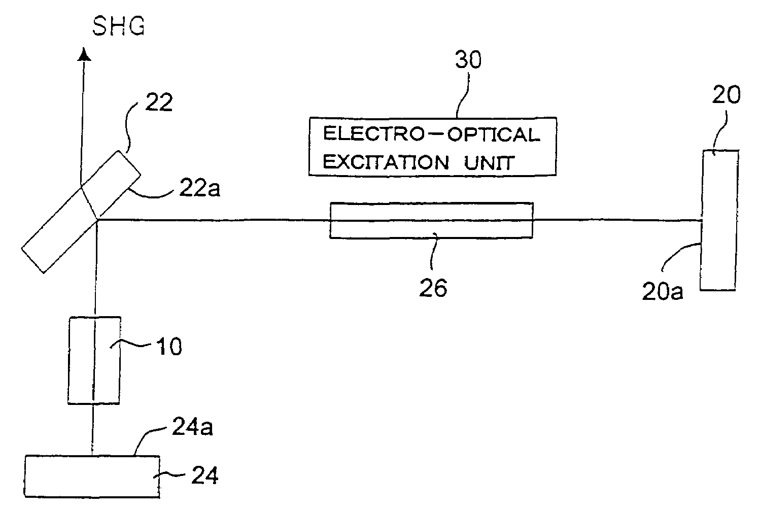
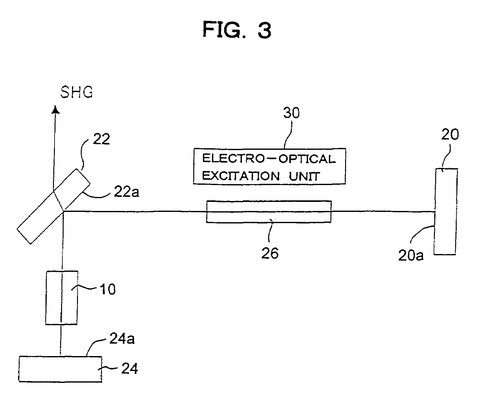
[0057]FIG. 3 shows a configuration of a principal part of a harmonic pulse laser apparatus according to one embodiment. This apparatus has a filded or triangular form optical resonator. More specifically, three (3) mirrors 20, 22, 24 are arranged in the triangular form; a solid-state laser active medium, for example, Nd:YAG rod 26 is disposed on a beam path between an intermediate mirror 22 and one of end mirrors 20; and a KTP crystal 10 is disposed on a beam path between the intermediate mirror 22 and the other end mirror 24. Both end mirrors 20 and 24 are optical resonator mirrors which have high reflectivity to the fundamental wavelength (e.g. 1064 nm) and are arranged optically opposed to each other via the intermediate mirror 22. The intermediate mirror 22 is a harmonic separator output mirror for outputting the second harmonic pulse laser beam to the outside of the resonator.

[0058]The active medium 26 is optically pumped by an electro-optic excitation unit 30. The electro-opti...

second embodiment

[0066]FIG. 4 shows a configuration of a principal part of a harmonic pulse laser apparatus according to another embodiment. In this apparatus, the end mirror 20, the harmonic separator output mirror 22, the active medium 26 and the KTP crystal 10 are arranged in the same straight line. More specifically, the active medium 26 is disposed nearer to the end mirror 20 and the KTP crystal 10 is disposed nearer to the harmonic separator output mirror 22. A principal surface 20a of the end mirror 20 is coated with a film which has high reflectivity to the fundamental wavelength (1064 nm). The principal surface 22a of the harmonic separator output mirror 22 is coated with a film which has high reflectivity to the fundamental wavelength (1064 nm) and a film which does not reflect the second harmonic (532 nm). Between the KTP crystal 10 and the active medium 26, a harmonic mirror 32 is disposed facing to the harmonic separator output mirror 22, and a principal surface 32a of the harmonic mirr...

third embodiment

[0073]FIG. 5 shows a configuration of a principal part of a harmonic pulse laser apparatus according to another embodiment. In this apparatus, the end mirrors 20 and 24, the harmonic separate output mirror 22, the active medium 26 and the KTP crystal 10 are arranged in the same straight line. More specifically, the active medium 26 is disposed nearer to the end mirror 20; the KTP crystal 10 is disposed nearer to the end mirror 24; and the harmonic separator output mirror 22 is disposed between the KTP crystal 10 and the active medium 26. However, the harmonic separator output mirror 22 is disposed such that an oblique angle, for example, 45 degrees is formed relative to an optical axis of the resonator. The principal surface of the harmonic separator output mirror 22, i.e., a surface 22a on the side of the KTP crystal is coated with a film which does not reflect the fundamental wavelength (1064 nm) and a film which has reflectivity to the second harmonic (532 nm).

[0074]In this appar...


PUM

PropertyMeasurementUnit
wavelengthaaaaaaaaaa
fundamental wavelengthaaaaaaaaaa
angleaaaaaaaaaa

Abstract

A KTP crystal is irradiated by a long-pulse fundamental wave pulse laser beam having a pulse width of 100 μs or longer typically output from a solid-state pulse laser such as a YAG pulse laser. In the KTP crystal, wavelength conversion is performed to generate a second harmonic pulse laser beam with a two times higher frequency, which long-pulse second harmonic pulse laser beam is in turn output for laser processing such as welding etc.

Description

BACKGROUND OF THE INVENTION[0001]1. Field of the Invention[0002]The present invention relates generally to a technology for wavelength conversion from a fundamental wavelength laser beam to a harmonic light beam and, more particularly, to a method and apparatus for generating a long-pulse harmonic pulse laser beam suited for laser processing such as welding etc.[0003]2. Description of the Related Art[0004]Recently, a laser is have been utilized in fields of manufacturing, especially welding, cutting and surface finishing. In fact, laser welding technology is increasingly becoming important because highly accurate and high speed processing can be achieved; a workpiece is affected by less thermal strain; and advanced automation can be enabled. Currently, a solid laser is used most frequently for laser welding and is a YAG laser which generates a light beam with a wavelength of about 1 μm. The YAG laser comprises a YAG (Y3Al5O12) crystal doped with rare earth active ions (such as Nd3+,...

Claims


Application Information

Patent Timeline
Patent Type & Authority Patents(United States)
IPC IPC(8): H01S3/10H01S3/13G02F1/37B23K26/21G02F1/355H01S3/081H01S3/109H01S3/16
CPCB23K26/063H01S3/109G02F1/3553H01S3/0815H01S3/1611H01S3/1643B23K26/0622D04B1/16D04B1/22D04B1/24D04B21/16D04B21/20D04B21/207D01D5/34D02G3/36D10B2501/042D10B2505/10D10B2503/02
Inventor NAKAYAMA, SHIN-ICHINAGASHIMA, TAKAHIROKASE, JUNPEI
Owner MIYACHI TECHNOS CORP
Why Eureka
Try Eureka