
Access point for constructing optical fiber-based high-speed wireless network system

a technology of high-speed wireless network and access point, which is applied in the direction of wireless communication, electromagnetic transceivers, network topologies, etc., can solve the problems of not being able to provide satisfactory service to a home or office environment, not yet perfected, and under development, so as to reduce manufacturing costs and reduce size

Inactive Publication Date: 2008-03-25
SAMSUNG ELECTRONICS CO LTD
View PDF4 Cites 102 Cited by
  • Summary
  • Abstract
  • Description
  • Claims
  • Application Information

AI Technical Summary

Benefits of technology

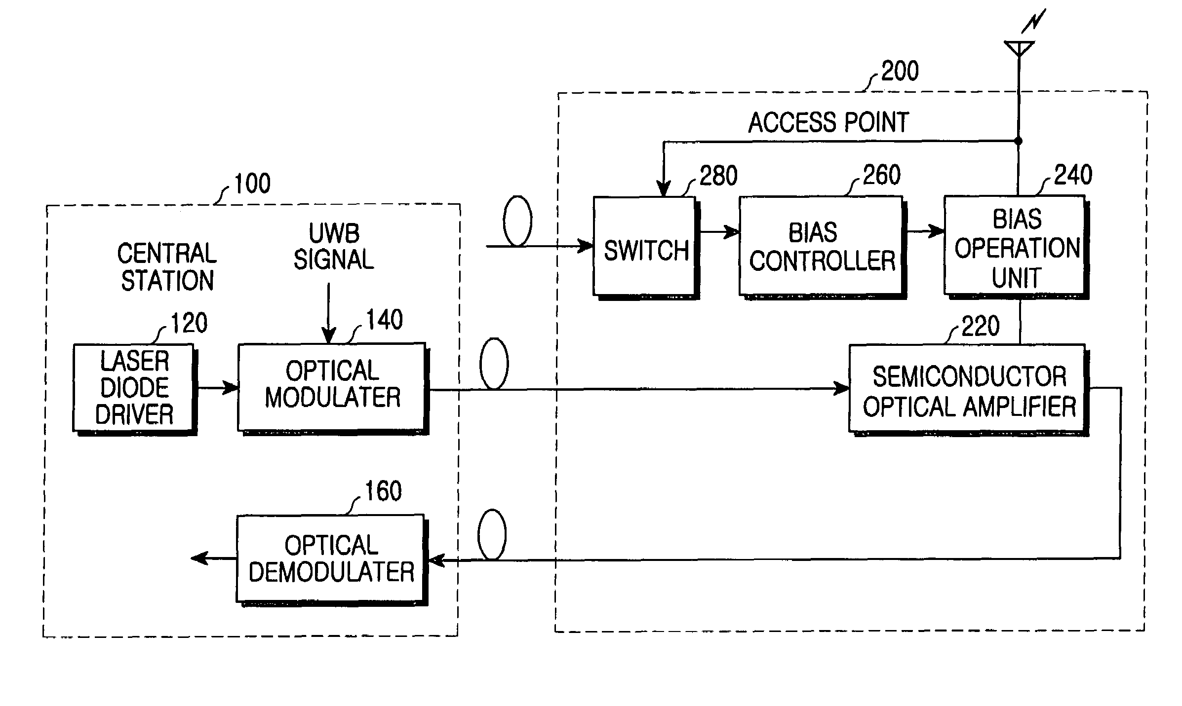
The present invention provides an access point for an ultra-wideband network system that can be more competitive in terms of size and cost. The access point can be constructed using a single optical device in a high-speed optical fiber-based wireless ultra-wideband network system with at least 100 Mbps. The access point has an antenna for transceiving signals for performing an ultra-wideband communication with outside devices and receiving communication requirement signals from the outside devices. The access point includes a semiconductor optical amplifier for selectively performing an optical detection function and an optical modulation function based on the communication requirement signals. The access point also includes a switch for selectively outputting a signal based on the communication requirement signals, a bias control unit for selectively outputting bias current with variable intensity based on the output of the switch, and a reverse bias that can be applied to the semiconductor optical amplifier for better optical detection. The integration of the optical detection and modulation functions in a single optical device reduces the size and cost of the network.

Problems solved by technology

Efforts to improve the transmission speed of such WLANs (e.g., a transmission speed of 54 Mbps at maximum in the 5 GHz band and a transmission speed more than 54 Mbps in millimeter wave band (30 GHz ˜300 GHz)) are under development, but not yet perfected.
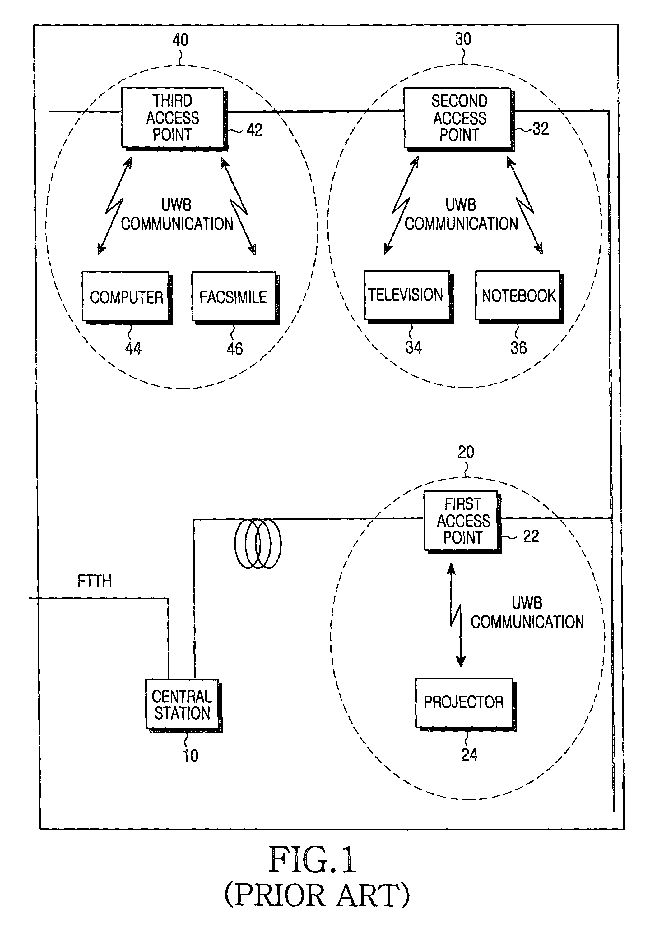
This limitation to the transmission speed of the WLAN may cause a bottleneck phenomenon in high speed and high capacity services provided through the existing WLAN by the fiber to the home (FTTH), so that it is nearly impossible to provide a satisfactory service to a home or office environment.
In the ultra wideband-based WLAN, high speed and high capacity services are possible, but service area is limited to 10 m.
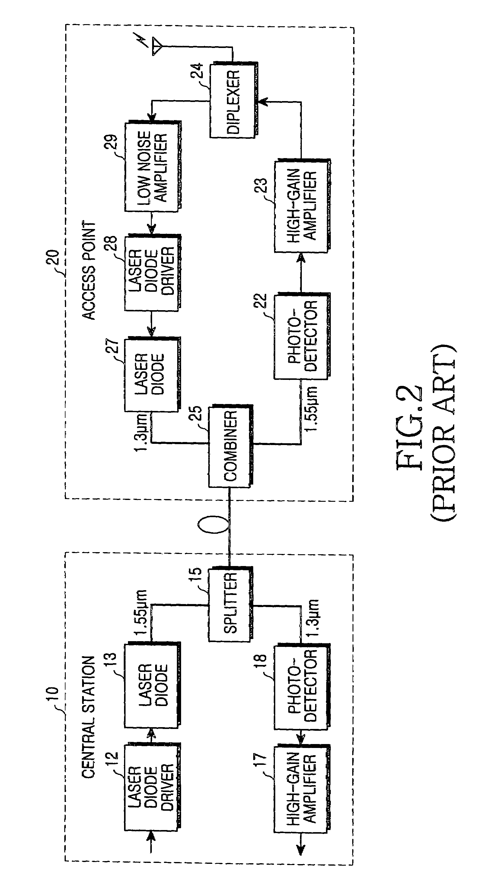
Further, the conventional AP consumes a large amount of power to drive many modules.
However, when sufficient optical power is not input to the EAM, which may be due to an optical loss between a CS and an AP, an AP using the EAM has difficulty in operating as an PD and an optical modulator.

Method used


Image

  • Access point for constructing optical fiber-based high-speed wireless network system
  • Access point for constructing optical fiber-based high-speed wireless network system
  • Access point for constructing optical fiber-based high-speed wireless network system

Examples


Embodiment Construction

[0038]Hereinafter, a preferred embodiment according to the present invention will be described with reference to the accompanying drawings. The same reference numerals are used to designate the same elements as those shown in other drawings. In the below description, many particular items, such as detailed elements of circuit, are shown, but these are provided for helping the general understanding of the present invention, it will be understood by those skilled in the art that the present invention can be embodied without the particular items. For the purposes of clarity and simplicity, a detailed description of known functions and configurations incorporated herein will be omitted as it may obscure the subject matter of the present invention.

[0039]FIG. 3 is a block diagram showing a embodiment of the present invention. As shown in FIG. 3, an ultra wideband high-speed wireless network system includes a central station (hereinafter, referred to as CS) 100 and an access point (hereina...


PUM


Abstract

An access point in an optical fiber-based high-speed optical wireless network is disclosed. The access point includes an antenna for receiving communication requirement signals, a switch for selectively outputting a corresponding signal according to the communication requirement signals, a bias control unit for selectively outputting bias current with variable intensity according to whether an output of the signal from the switch exists or not, on the basis of a threshold current; a bias operation unit for outputting input signals to the antenna when an input bias current is smaller than the threshold current and for outputting signals received by the antenna when an input bias current is larger than the predetermined threshold current, and a semiconductor optical amplifier for selectively performing an optical detection function of converting optical signals, which have been received through a first optical fiber from an central station, into electrical signals and sending the converted electrical signals to the bias operation unit, when a current smaller than the threshold current is input to the bias operation unit, and an optical modulation function of transmitting signals output from the bias operation unit through a second optical fiber to the central station, when a current larger than the threshold current is input to the bias operation unit.

Description

CLAIM OF PRIORITY[0001]This application claims priority to an application entitled “Access point for constructing optical fiber-based high-speed optical wireless network system,” filed in the Korean Intellectual Property Office on Jun. 30, 2003 and assigned Serial No. 2003-43855, the contents of which are hereby incorporated by reference.BACKGROUND OF THE INVENTION[0002]1. Field of the Invention[0003]The present invention relates to an access point in a local area communication network system, more particularly to an access point utilizing a semiconductor optical amplifier capable optical fiber-based ultra-wideband (UWB) wireless communication in an indoor local area communication network system having a transmission speed of at least 100 Mbps using an ultra-wideband communication method.[0004]2. Description of the Related Art[0005]Ultra-wideband communication technology is a wireless communication technology for transmitting large amounts of digital data with a low power in a short...

Claims


Application Information

Patent Timeline
Patent Type & Authority Patents(United States)
IPC IPC(8): H04B10/00H04L12/28H04B10/27H04B10/40H04B10/50H04B10/54H04B10/60H04J14/08H04W84/10H04W84/12H04W88/08H04W92/12
CPCH04B10/272H04L12/28
Inventor LEE, JONG-HUNOH, YUN-KYUNGLEE, SANG-ILKWON, SEO-WONLEE, JONG-HWAOH, YUN-JE
Owner SAMSUNG ELECTRONICS CO LTD
Learn More