Microscope turret mounted laser EPI-illumination port

a laser and microscope technology, applied in the field of adapting a laser to a microscope, can solve the problems of fertility failure, significant impediment in the tougher layers,

Inactive Publication Date: 2008-04-15
HAMILTON THORNE
View PDF11 Cites 23 Cited by
  • Summary
  • Abstract
  • Description
  • Claims
  • Application Information

AI Technical Summary

Benefits of technology

[0081]In application to the drilling of ZP, it is a further advantage of the invention that the size of the hole to be drilled is represented well by the diameter of the 140° C. peak-temperature isotherm. Thus, for any conditions of laser power and laser pulse duration, the diameter of the Tmax=140° C. isotherm gives the diameter of the hole that will be drilled in the ZP.
[0082]An example of the invention is shown in the FIG. 7, in which the isotherms are shown superimposed on a scale image of an oocyte indicating the peak thermal excursion that will be experienced at different distances from the laser beam focus by different parts of the oocyte.

Problems solved by technology

Consequently, when the time comes for the embryo to emerge from the ZP, there may be a significant impediment in the tougher layers, which have to be traversed.
If the embryo fails to hatch in the limited time available, it will be lost and fertility will fail.

Method used


Image

  • Microscope turret mounted laser EPI-illumination port
  • Microscope turret mounted laser EPI-illumination port
  • Microscope turret mounted laser EPI-illumination port

Examples


example 1

Laser Module, Microscope Specifications, and Design

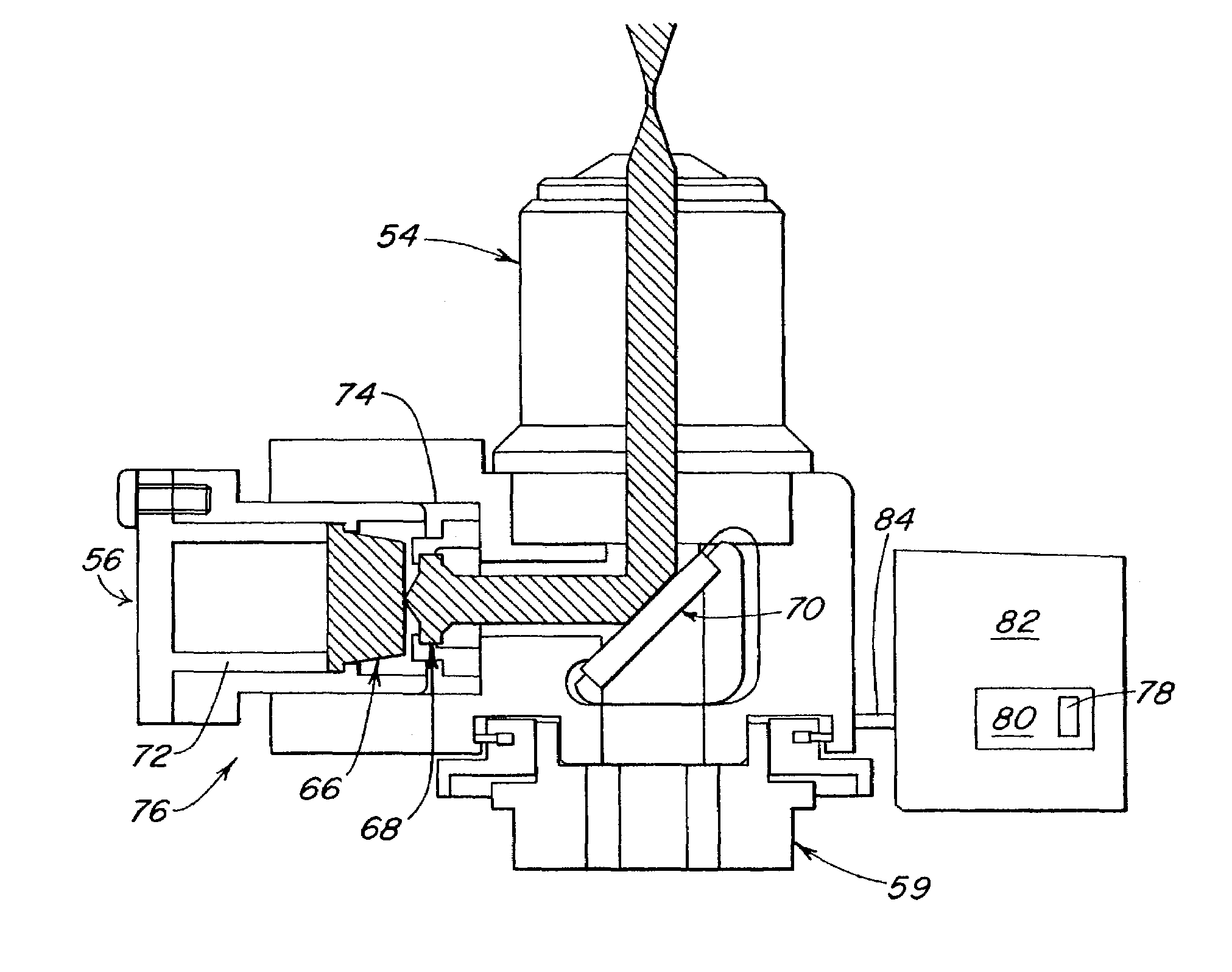
[0084]A Nikon TE-300 laser-equipped inverted microscope was used, which has the IR laser beneath the stage. Laser light proceeds up through the objective and is focused on the target. The laser module (ZLTS, Hamilton Thorne Research, Beverly, Mass.) has maximum power 200 mW at λ=1480 nm, and is utilized in pulsed mode. Peak transmitted laser power through the objective is approximately 140 mW. Pulse duration is adjustable in half millisecond increments from 0.5 to 25 ms. In addition to the laser diode itself, the laser module includes control board, adjustable collimating lens and dichroic mirror, and is inter-locked to prevent potentially hazardous operation.

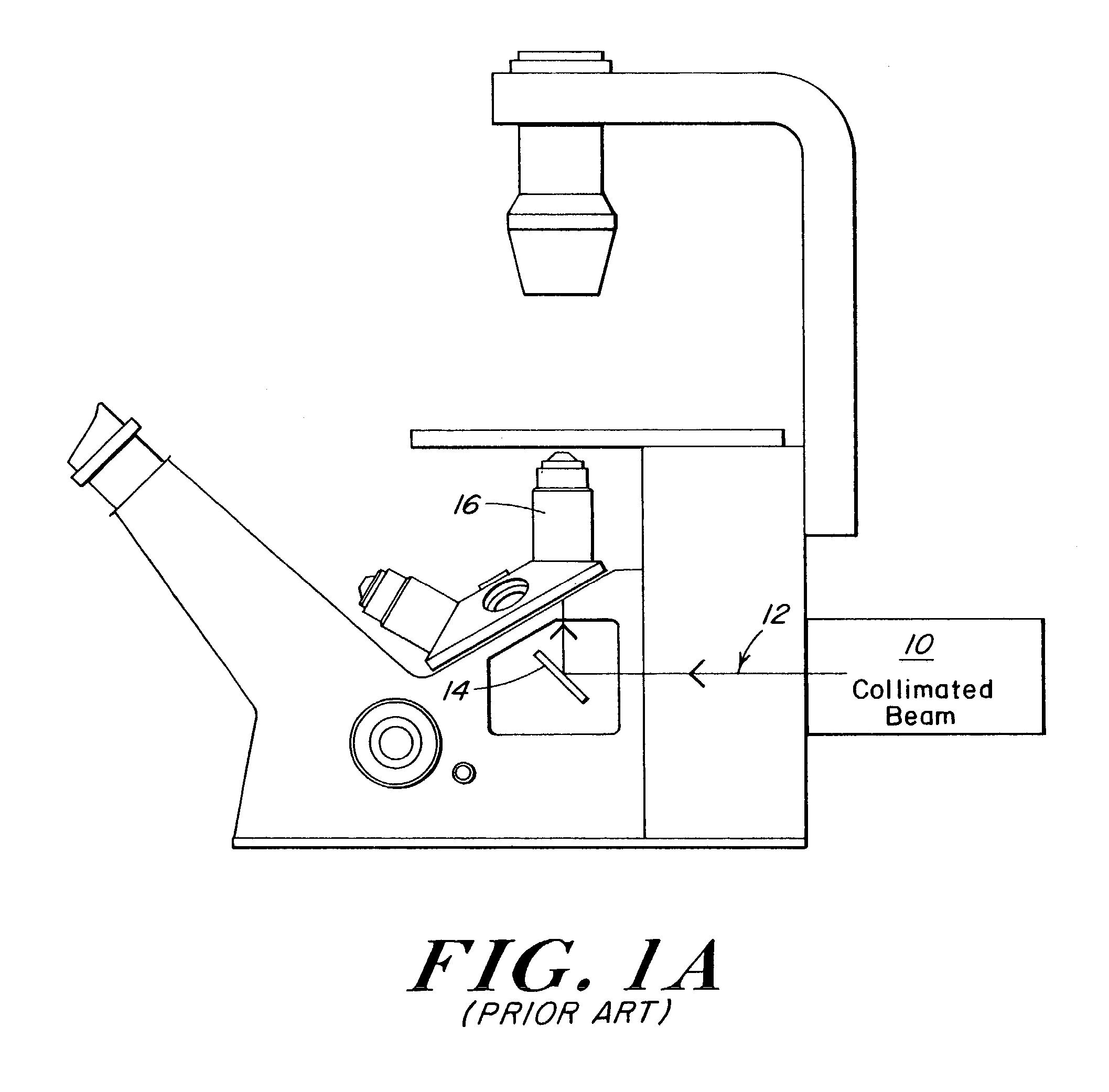
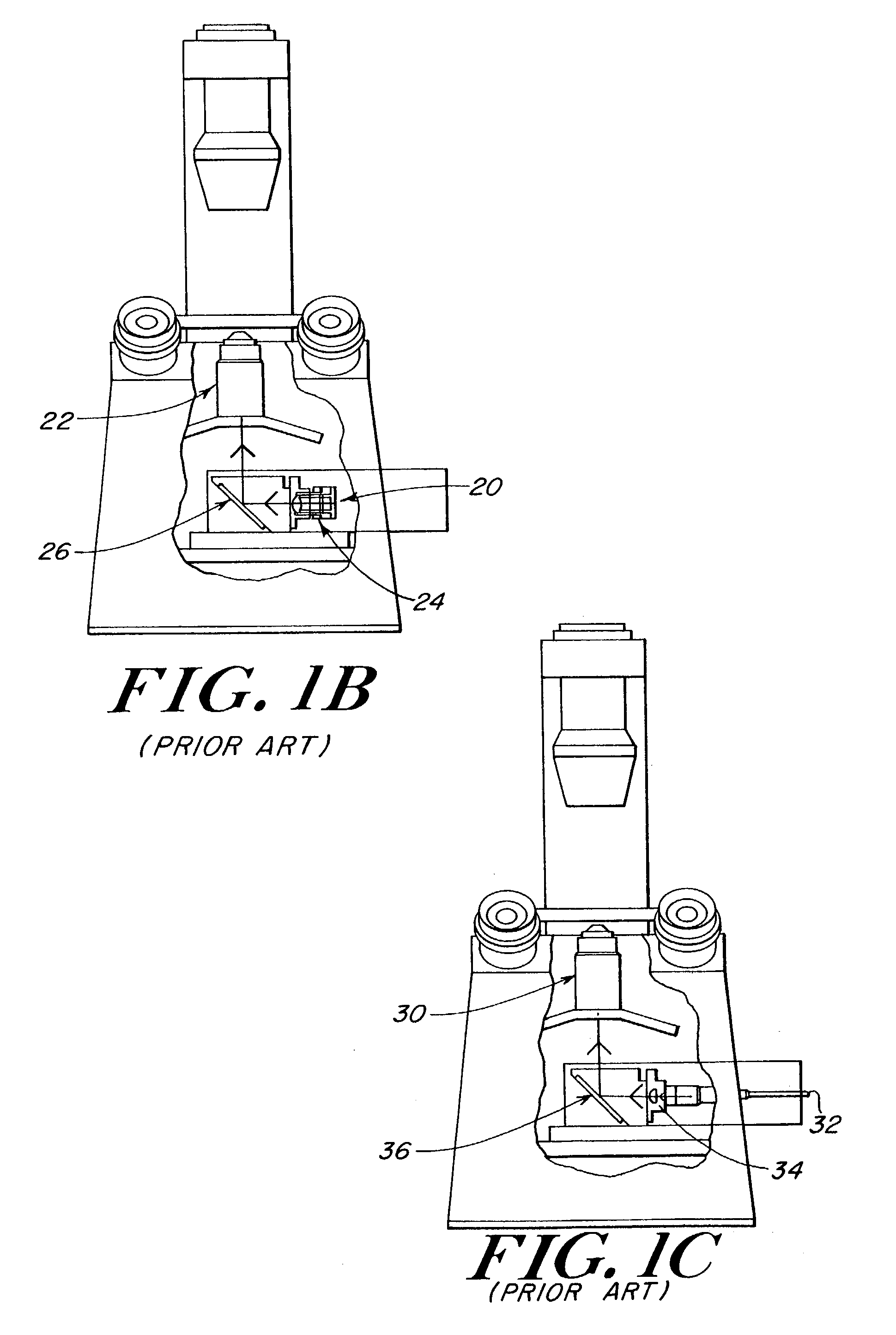
[0085]The laser module fits into the microscope filter cube slot under the stage and the beam is deflected by a dichroic mirror along the optic axis of the microscope. The nearly collimated beam is directed toward the back aperture of a 40×, 0.60 numerical aperture (NA) objecti...

example 2

Laser-Assisted Zona Dissection with Bovine Eggs

[0087]Bovine eggs are readily available. They constitute a useful and cost effective model for testing laser-assisted zona drilling protocols. The Nikon TE300 inverted microscope is used with illumination source and condenser above specimen and objective below. The Petrie dish specimen chamber (wall thickness 1 mm, diameter 50 mm) is on a motorized stage. The eggs settle at the bottom of the dish and the objective is focused on the edge of the ZP, about 75 μm into the medium.

[0088]A typical zona drilling is shown in FIG. 8 for a bovine oocyte. The egg diameter is about 150 μm and the thickness of the zona pellucida, the translucent shell surrounding the egg, is about 12 μm. The laser power was set to 100 mW delivered at the focal point and three points in the ZP corresponding to pulse duration 1.5, 3, and 4.5 ms. Beam diameter to 1 / e2 was 6.2 μm, independent of beam power. The hole diameters are 4.3, 7.8, and 10.5 μm; the hole diameter ...

example 3

Thermal Predictions

[0091]Standard Conditions

[0092]The objective (NA=0.6, 40×, infinity corrected) used transmits 71% of the incident energy at λ=1480 nm. The typical laser beam power arriving at the vicinity of the ZP following transmissive, reflective, and attenuation loss is calculated as 100 mW. The typical beam focal radius is calculated as a=3 μm, assuming the beam is passing up through an inverted microscope into medium of refractive index n=1.333. The thermal history or isothermal contour expected along the path of the laser beam and especially in the vicinity of the pre-embryo is derived as described below.

[0093]Thermal Constants and Source Function Geometry

[0094]Using medium comprised of almost pure water and the cellular material is approximately 80% water, the infrared absorptances in the medium and cell at λ=1480 nm are approximately that of H2O and cannot be significantly lower. Similarly, the thermal conductivity of the material will not be higher than that of water. B...


PUM


Abstract

An optical injection system for use in conjunction with a microscope having a turret supporting an objective having an optical path is provided. The optical injection system includes a dichroic mirror disposed between the turret and the objective, along the optical path. A collimating lens is further provided having an optical path directed to intersect the dichroic mirror. A laser source is positioned to project a laser beam through the collimating lens and along the collimating lens optical path. The laser can be used in conjunction with the microscope for a number of microsurgery applications. A method for calculating and displaying the isothermal contours of the energy produced by a laser in a sample is also provided.

Description

RELATED APPLICATION[0001]This application claims priority to co-pending U.S. Provisional Application No. 60 / 329,769, filed on Oct. 16, 2001, and co-pending U.S. Provisional Application No. 60 / 366,774, filed on Mar. 22, 2002, incorporated herein in their entirety by this reference.FIELD OF THE INVENTION[0002]The present invention relates to an adaptation of a laser to a microscope. More specifically, a device is disclosed that fits between the microscope objective and the microscope nosepiece turret for introducing laser energy into the optical path and on to the microscope sample.[0003]The present invention also relates to a method for calculating and displaying the isothermal contours produced by a laser in a sample. The method can be carried out using the described microscope and a computing apparatus for performing the calculations and displaying the isothermal contours.BACKGROUND OF THE INVENTION[0004]Recent advances in biology and medicine have led to the development of laser b...

Claims


Application Information

Patent Timeline
Patent Type & Authority Patents(United States)
IPC IPC(8): G02B21/06G02B21/00G02B21/32
CPCG02B21/06G02B21/32G02B21/0088
Inventor KENNY, THOMAS G.
Owner HAMILTON THORNE
Why Eureka
Try Eureka