Automated pattern recognition of imprint technology

a technology of automatic pattern recognition and imprint technology, applied in the field of imprint lithography, can solve the problems of increasing cost, difficulty in manual adjustment, slow adjustment, etc., and achieve the effect of reducing the cost of imprint lithography, speeding up the speed of imprint lithography, and improving the quality of imprint lithography

Inactive Publication Date: 2008-04-22
GEOFENCE DATA ACCESS CONTROLS +1
View PDF21 Cites 88 Cited by
  • Summary
  • Abstract
  • Description
  • Claims
  • Application Information

AI Technical Summary

Benefits of technology

[0026]Embodiments of the present invention provide for higher throughput and reduced cost in imprint lithography. The automatic adjustment of the droplet pattern based on images of the spreading of prior droplet patterns allows for faster imprint lithography than was possible with manual adjustment of the droplet pattern. Once the droplet pattern has been adjusted based on the digital images the droplets spread more quickly and more evenly. Subsequent patterns of liquid may be imprinted and hardened (e.g., by UV exposure through the template) more quickly and with a higher yield than previously obtainable using manual droplet pattern adjustment.

Problems solved by technology

Nano-imprint lithography resolution is primarily limited by the resolution of the template fabrication process.
One problem with the above technique occurs as a result of non-uniform spreading of the monomer drops after contact with the patterned surface of the mesa.
Unfortunately, such manual adjustment is difficult and slow, which increases cost and reduces yield.

Method used


Image

  • Automated pattern recognition of imprint technology
  • Automated pattern recognition of imprint technology
  • Automated pattern recognition of imprint technology

Examples


Embodiment Construction

[0014]Although the following detailed description contains many specific details for the purposes of illustration, anyone of ordinary skill in the art will appreciate that many variations and alterations to the following details are within the scope of the invention. Accordingly, the exemplary embodiments of the invention described below are set forth without any loss of generality to, and without imposing limitations upon, the claimed invention.

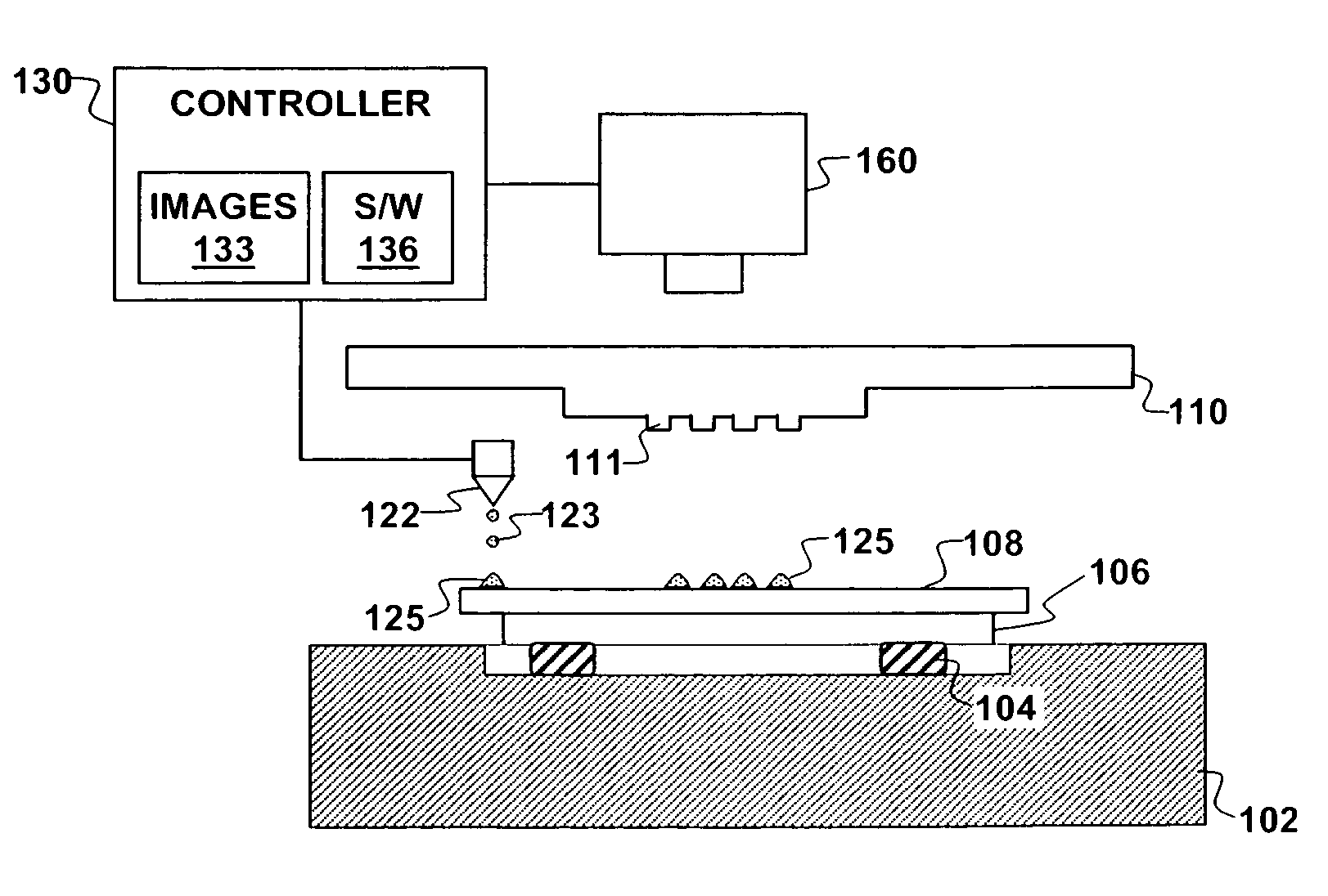
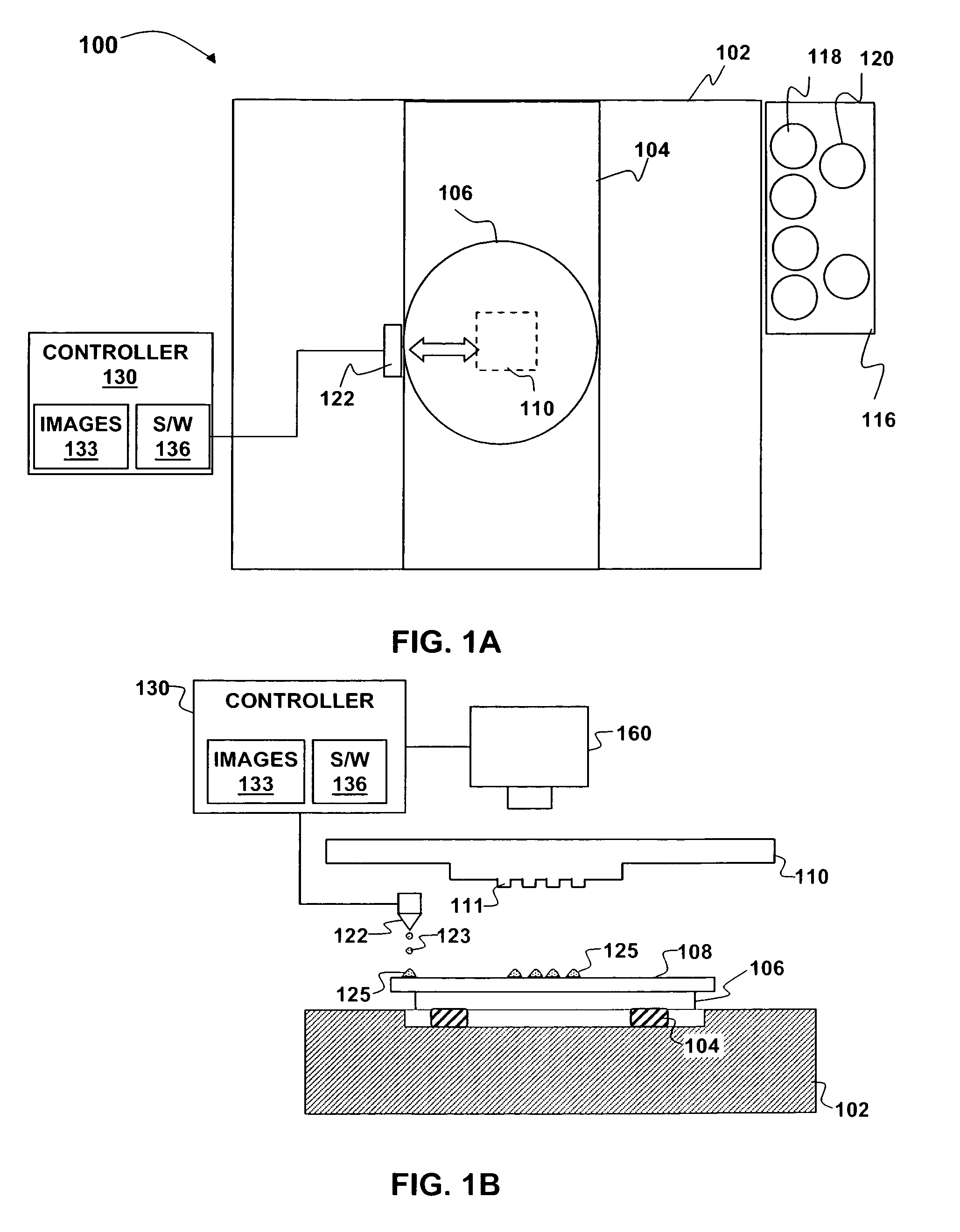
[0015]According to a first embodiment of the present invention, an apparatus for control of spreading of liquid drops is shown in FIGS. 1A-1B. The apparatus 100 one or more image capture devices such as one or more digital cameras 160 coupled to a controller 130. The apparatus 100 also includes a granite stage 102 and a carriage 104 placed on the granite stage 102. The carriage 104 carries a chuck 106. A substrate 108 such as a semiconductor wafer is placed on the chuck 106. The system 100 also includes a droplet dispenser 122, e.g., a paral...


PUM


Abstract

An apparatus and method for control of spreading of liquid drops are disclosed. An initial pattern of drops of liquid is deposited on a first surface. A second surface is brought into sufficient contact with the initial pattern of the drops that the liquid starts to spread. Two or more digital images of the liquid are captured after it begins to spread. A digital analysis is performed on these images to determine whether one or more portions of the initial pattern of drops require more or less liquid. A subsequent pattern of liquid droplets is adjusted based on the digital analysis.

Description

FIELD OF THE INVENTION[0001]This invention generally relates to imprint lithography and more particularly to the use of automated pattern recognition in to adjust resist droplet patterns in imprint lithography.BACKGROUND OF THE INVENTION[0002]Nano-imprint lithography is based on embossing adapted to the needs of semiconductor processing. Nano-imprint lithography is essentially a micromolding process in which the topography of a template patterns a photoresist on a wafer. In photolithography, by contrast, the resist is patterned by optical exposure and development. Unlike photolithography, imprint lithography does not use reduction optics. Instead, the size of the template determines the size of the pattern. Thus masks for nano-imprint lithography are often referred to as 1X masks. One advantage of nano-imprint lithography is that the parameters that limit resolution in classic photolithography (including wavelength and numerical aperture) do not apply. Nano-imprint lithography resol...

Claims


Application Information

Patent Timeline
Patent Type & Authority Patents(United States)
IPC IPC(8): B41J3/00
CPCB41J3/407B41J3/44B41J3/50B82Y10/00B82Y40/00G03F7/0002
Inventor SNYDER, BRYAN L.
Owner GEOFENCE DATA ACCESS CONTROLS
Why Eureka
Try Eureka