
System and method for producing light with organic light-emitting devices

a technology of organic light and light-emitting devices, applied in the direction of discharge tube luminescnet screens, other domestic articles, natural mineral layered products, etc., can solve the problems of longer wavelength light generation, improve the stability of white light emission over time, and improve the control of the variation in the composition of white light. , the effect of improving the stability of white light emission

Active Publication Date: 2008-04-22
VERSITECH LTD
View PDF25 Cites 24 Cited by
  • Summary
  • Abstract
  • Description
  • Claims
  • Application Information

AI Technical Summary

Benefits of technology

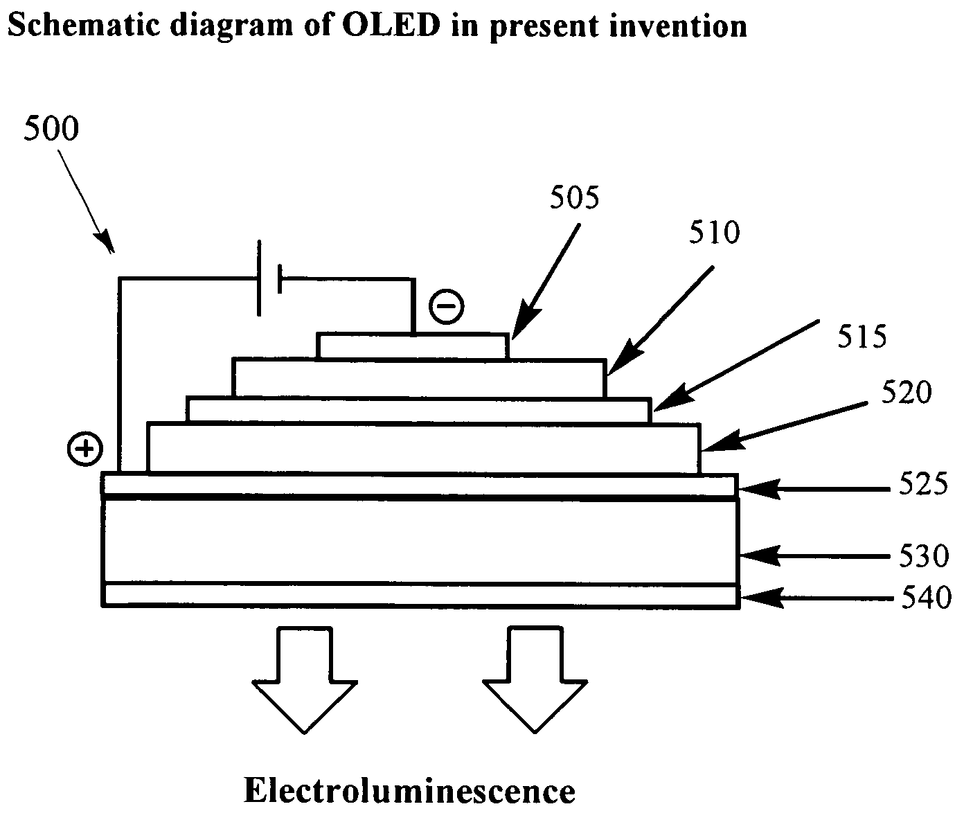
[0013]The present invention is directed to OLEDs comprising an emissive layer that requires only a single electrophosphorescent emitter (but can contain more) and comprises at least one transition metal complex comprising two bidentate NO-type ligands or a tetradentate NOON-type ligand as the electrophosphorescent emitters. Embodiments with OLED devices of the invention exhibit improved stability of white light emission over time and better control over the variation in the composition of white light due to removal of the errors from imbalance of multiple dopants providing widely different color emissions. The OLED devices of the present invention also exhibit low turn-on voltages, high luminance, high quantum efficiencies, and may be modified by simply changing the dopant concentration to exhibit colors other than white light.

Problems solved by technology

Moreover, Adamovich et al. reported that aggregation of such dopants results in generation of longer wavelength light.

Method used


Image

  • System and method for producing light with organic light-emitting devices
  • System and method for producing light with organic light-emitting devices
  • System and method for producing light with organic light-emitting devices

Examples


example 1

[0105]Example 1 shows the physical properties of non-limiting illustrative emissive materials corresponding to dopant complexes 1-3 of the present invention.

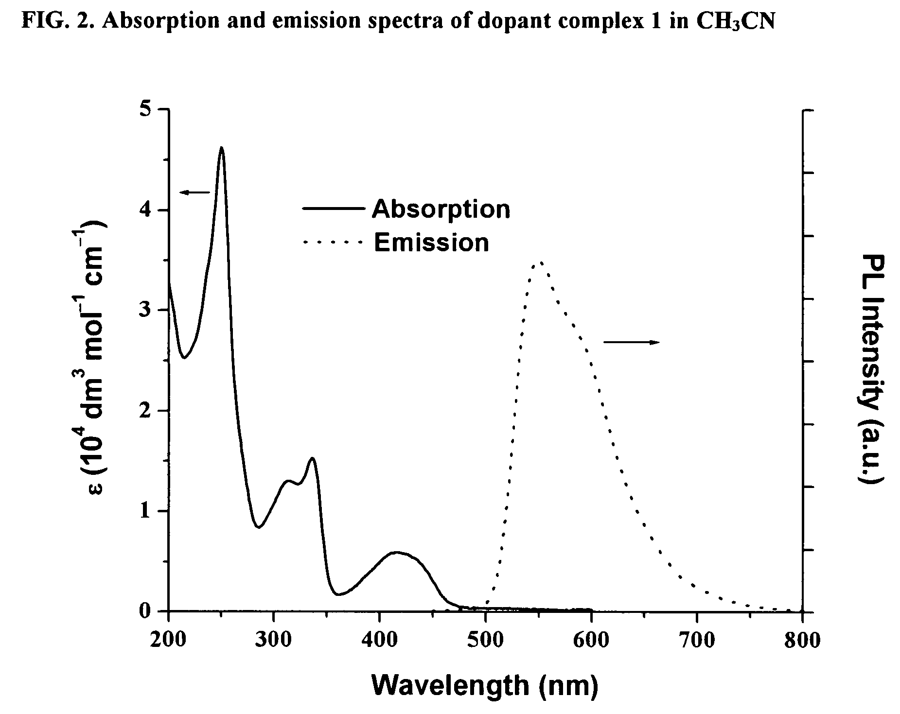
[0106]The absorption and photoluminescence properties of dopant complexes 1-3 are provided in Table 2. Dopant complexes 1-3 exhibit similar absorption features and a low-energy band is observed at λmax 417 to 432 nm. The photoluminescence (PL) spectrum is substantially independent of excitation wavelength from 300 to 450 nm. At room temperature, strong yellow PL is obtained with quantum yields (Φ) up to 0.19 in CH3CN. The emission lifetimes of the dopant complexes range from 0.46 to 3.5 μs.

[0107]

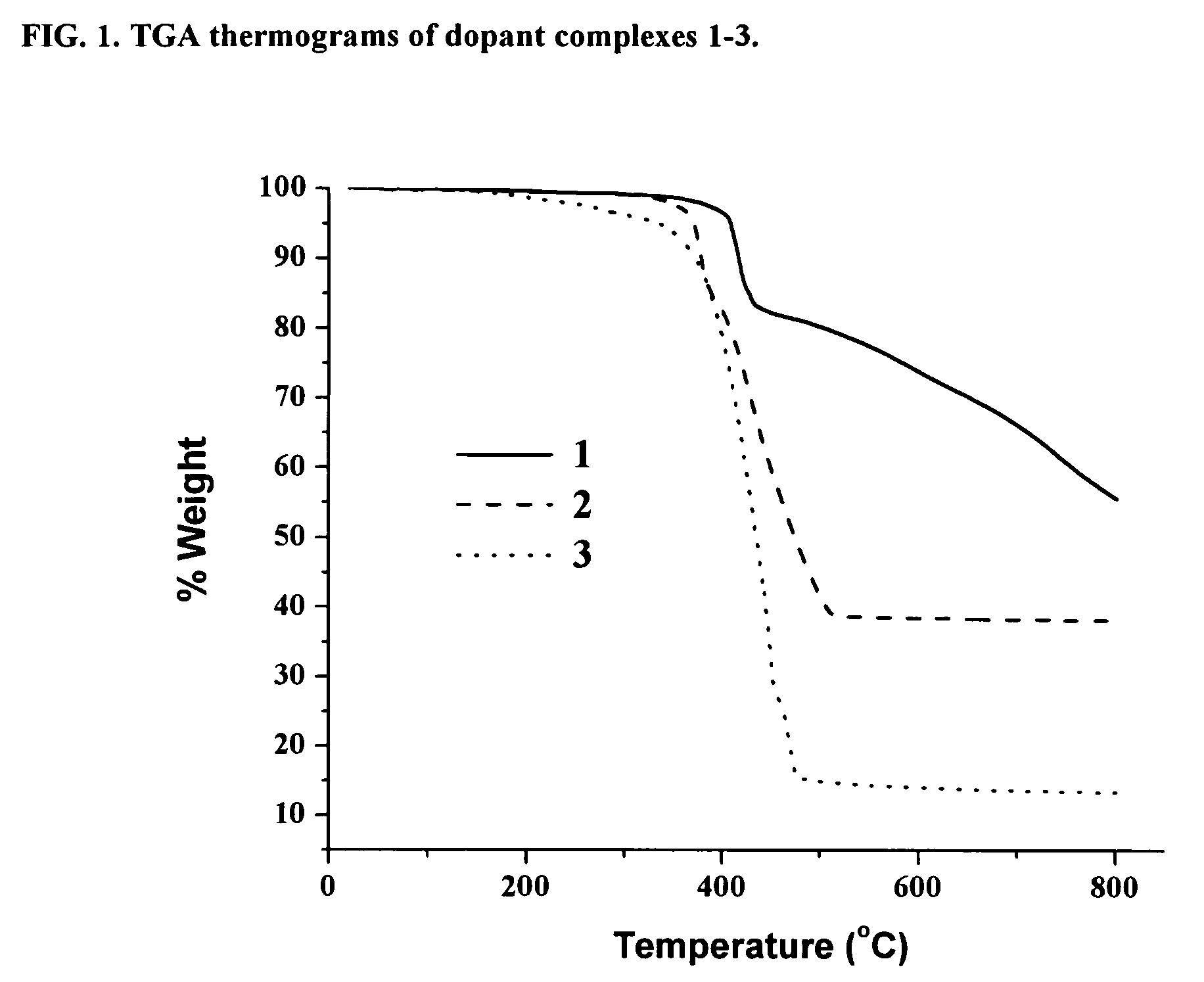
TABLE 2Physical characterization of dopant complexes 1-3.Dopantλabs (nm)λem, sol.Φem, sol.λem solid statecomplex[ε, 104 dm3 mol−1 cm−1](nm)a[τ, (μs)]b(nm)cTd (° C.)d1250 [4.62], 314 [1.30],550, 580e 0.19 [3.5]548e, 594,406336 [1.53], 417 [0.59]648e2250 [4.08], 320 [0.96],5920.087 [0.46]598369340 [1.12], 420 [0.52]3249 [4.60], 316 [1.16],...

example 2

[0112]Example 2 illustrates a non-limiting method for preparing OLED A of the present invention. ITO glass with sheet resistance of about 20 Ω / square cm was cleaned three times in sequence with detergent solution, deionized water, acetone, isopropanol, methanol and deionized water, followed by ultra-violet-ozone cleaner. The devices were then fabricated using a standard thermal evaporation method by laminating each layer in sequence at a deposition rate of about 2 Å / sec or about 5 Å / sec using a base pressure of about 5×10⁻⁶ Torr and without breaking vacuum between different vacuum deposition sequences. The emissive layer was prepared by fixed-current heating of crucibles containing the host and dopant complex to provide deposition rates of 9 Å / sec and 1 Å / sec for the host and dopant complex, respectively. Two crystal oscillators were used to monitor the deposition rates. The fixed-current heating provided an emissive layer containing about 3.2 wt. % dopant complex.

[0113]The structur...


PUM

PropertyMeasurementUnit
internal quantum efficienciesaaaaaaaaaa

Abstract

Disclosed are emissive materials of formula (I) or (II), comprising two bidentate NO-type ligands, or a tetradentate NOON-type ligand, and a transition metal. The emissive materials are useful as electrophosphorescent emitters in organic light-emitting devices. Also disclosed are methods for preparing organic light-emitting diodes comprising these emissive materials, and the use of such diodes as white and yellow organic light-emitting devices.

Description

FIELD OF THE INVENTION[0001]The present invention relates to efficient organic light-emitting devices which comprise a transition metal complex, the transition metal complex comprising a bidentate NO-type ligand, or tetradentate NOON-type ligand and a transition metal atom as the electrophosphorescent emitter. The invention also relates to methods for preparing thin film organic light-emitting devices and their use in applications such as flat-panel displays, liquid crystal displays and plasma panel displays.BACKGROUND OF THE INVENTION[0002]Organic light-emitting devices (OLEDs) are finding applications as next-generation flat-panel displays (FPDs), liquid crystal display (LCDs), and plasma display panels (PDPs). This has been driven by their favorable properties including lightweight, fast video response and low power consumption. To this end, organometallic compounds exhibiting electroluminescence are particularly attractive for electrophosphorescent applications, since both the l...

Claims


Application Information

Patent Timeline
Patent Type & Authority Patents(United States)
IPC IPC(8): B32B19/00H01J63/04C09K11/06H01L51/00H01L51/50H05B33/14
CPCC09K11/06H01L51/0087H05B33/14C09K2211/1007C09K2211/1011C09K2211/185C09K2211/187H01L51/0059H01L51/0077H01L51/5016H01L51/5036Y10S428/917H10K85/631H10K85/30H10K85/346H10K50/125H10K50/11H10K2101/10
Inventor CHE, CHI-MINGCHAN, SIU-CHUNG
Owner VERSITECH LTD
Learn More