
Fabrication methods for micro compounds optics

a technology of micro-compounds and optics, applied in the field of fabrication techniques, can solve problems such as problems

Inactive Publication Date: 2008-04-29
CARL ZEISS X RAY MICROSCOPY
View PDF2 Cites 40 Cited by
  • Summary
  • Abstract
  • Description
  • Claims
  • Application Information

AI Technical Summary

Benefits of technology

The patent text describes a method for fabricating a compound optic for short wavelength radiation, which can be used in applications such as laser systems. The method involves removing material from a substrate to create a surface profile of the first optical element of the compound optic, which can be done mechanically or chemically. The second optical element is then formed on the substrate, using the surface profile as a reference. The invention also includes a method for aligning the two optical elements during fabrication and maintaining the alignment during operation. The optical element comprises concentric rings for focusing a beam of short wavelength radiation and segments extending at least partially radially between the rings to support them. A frame is also provided to extend around at least a portion of the concentric rings and support them in the frame. The technical effects of the invention include improved precision in the fabrication of compound optics for short wavelength radiation and better alignment of the optical elements during fabrication and operation.

Problems solved by technology

Challenges arise, however, when fabricating compound optics and Fresnel refractive optics for these short wavelength radiation applications.

Method used


Image

  • Fabrication methods for micro compounds optics
  • Fabrication methods for micro compounds optics
  • Fabrication methods for micro compounds optics

Examples


Embodiment Construction

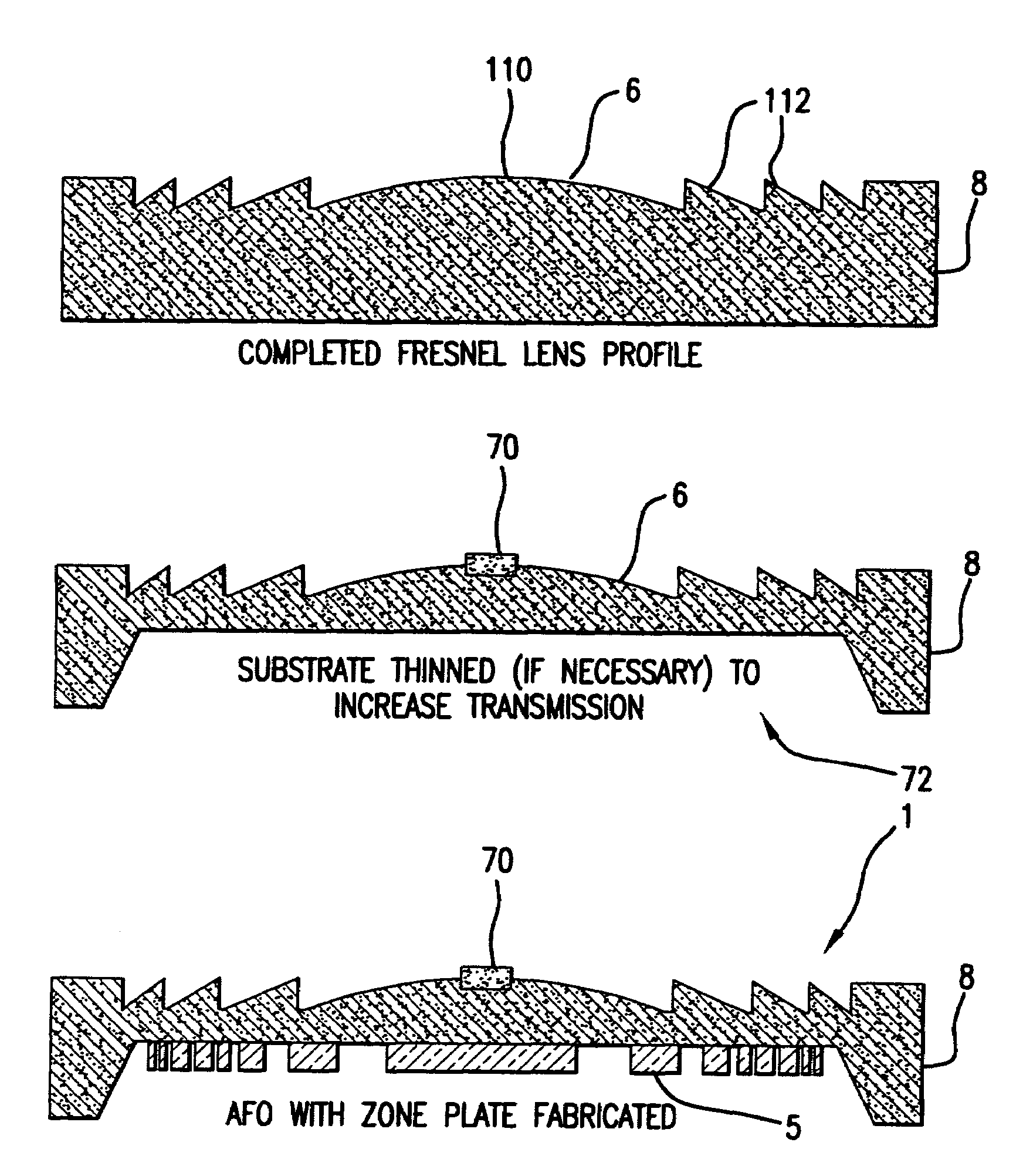
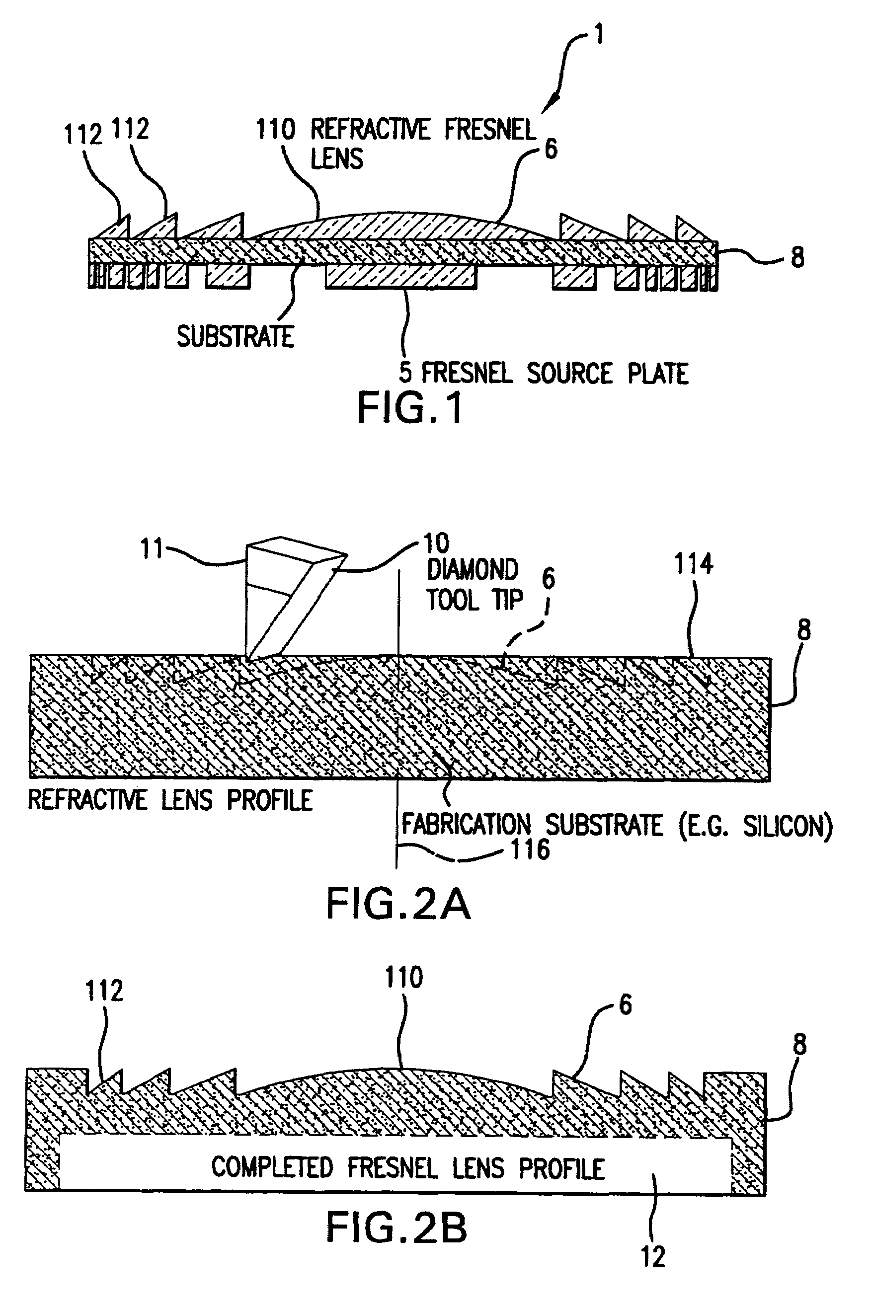
[0023]FIG. 1 shows a compound optic or AFO 1, to which the present invention is applicable in one example.

[0024]The exemplary compound optic 1 comprises a diffractive Fresnel zone plate element 5 and one or more refractive Fresnel lens elements 6.

[0025]The compound optic 1 is shown fabricated on a single substrate 8. In practice, the different elements 5, 6 can also be fabricated on separated substrates, in other embodiments.

[0026]In the example in which the compound optic 1 is an. AFO, it includes a primary focusing element, which is the diffractive Fresnel zone plate 5, and chromatic dispersion compensating elements which is the refractive lenses 6. The refractive lens 6 compensates for the chromatic dispersion of the zone plate 5 but with no or very small focusing effect.

[0027]For micro-imaging applications involving short wavelength radiation, i.e., radiation in the wavelength range of 0.02 nanometers (nm) to 20 nm, the width of the segments in the refractive lens 6 typically ra...


PUM

PropertyMeasurementUnit
wavelengthsaaaaaaaaaa
widthaaaaaaaaaa
wavelength rangeaaaaaaaaaa

Abstract

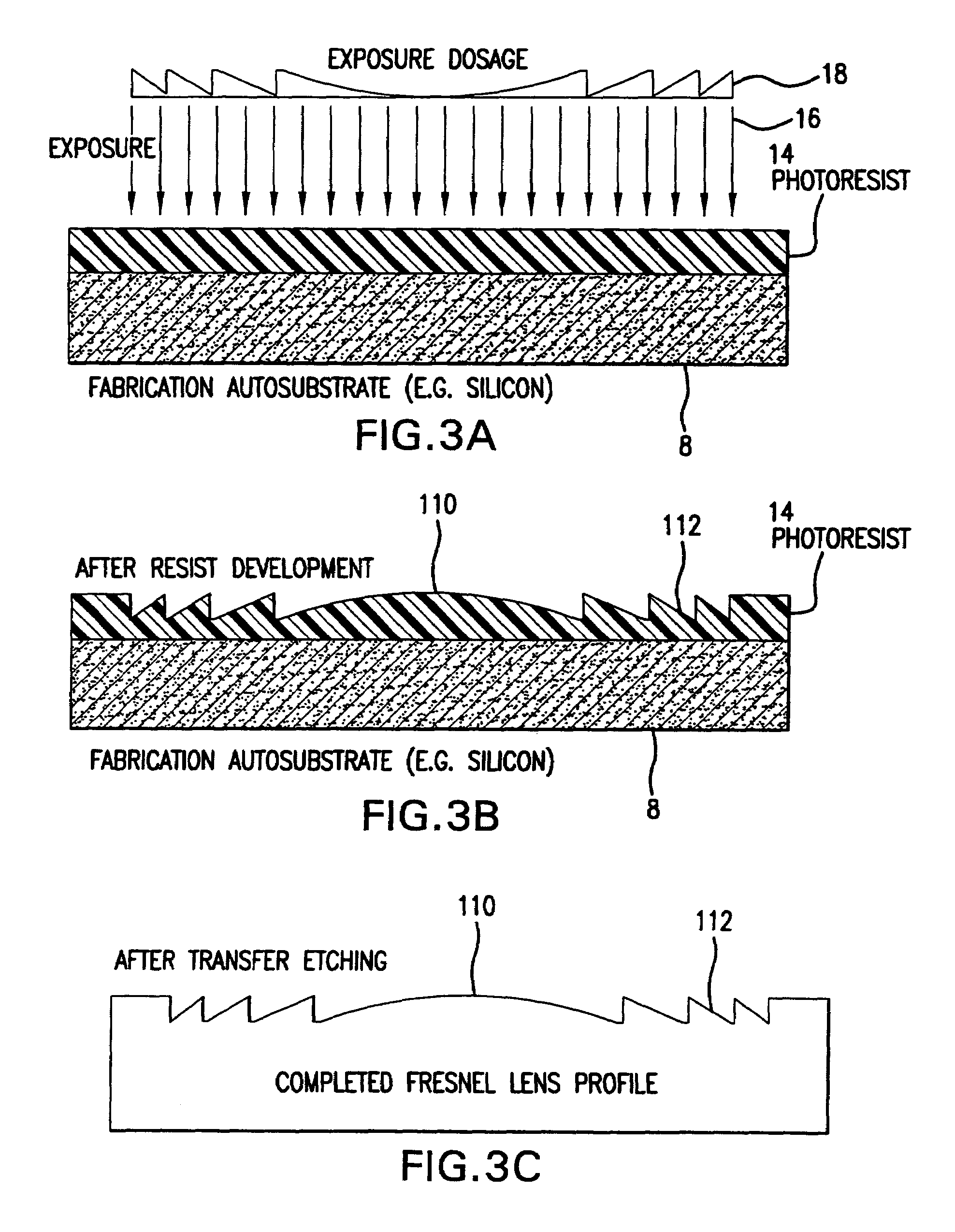
Methods for fabricating refractive element(s) and aligning the elements in a compound optic, typically to a zone plate element. The techniques are used for fabricating micro refractive, such as Fresnel, optics and compound optics including two or more optical elements for short wavelength radiation. One application is the fabrication of the Achromatic Fresnel Optic (AFO). Techniques for fabricating the refractive element generally include: 1) ultra-high precision mechanical machining, e.g,. diamond turning; 2) lithographic techniques including gray-scale lithography and multi-step lithographic processes; 3) high-energy beam machining, such as electron-beam, focused ion beam, laser, and plasma-beam machining; and 4) photo-induced chemical etching techniques. Also addressed are methods of aligning the two optical elements during fabrication and methods of maintaining the alignment during subsequent operation.

Description

RELATED APPLICATIONS[0001]This application claims priority to U.S. Provisional Appl. No. 60 / 419,331, filed Oct. 17, 2002, which is incorporated herein by reference in its entirety.BACKGROUND OF THE INVENTION[0002]The present invention pertains generally to fabrication techniques to be used for fabricating micro refractive, such as Fresnel, optics and compound optic comprising two or optical elements for short wavelength radiation. One application is the fabrication of the (AFO) described in U.S. patent application Ser. No. 10 / 134,026, which is incorporated herein by this reference in its entirety.[0003]The Achromatic Fresnel Optic (AFO) is a multi, such as two, element compound optic that is comprised of a diffractive Fresnel zone plate and a one or more refractive Fresnel lenses. The optic is described in U.S. patent application Ser. No. 10 / 134,026 (U.S. Pat. Appl. Publ. No. US 2005 / 0168820 A1), which is incorporated herein by this reference in its entirety. Further uses for the op...

Claims


Application Information

Patent Timeline
Patent Type & Authority Patents(United States)
IPC IPC(8): G02B27/44G02B3/08G03F7/00
CPCG02B3/08G02B27/4211G03F7/0005G02B27/4272Y10S438/975
Inventor YUN, WENBINGWANG, YUXINFESER, MICHAELLYON, ALAN
Owner CARL ZEISS X RAY MICROSCOPY
Learn More