Diamond lathing cutter track tracing method

A diamond turning and tool path technology, applied in the direction of comprehensive factory control, digital control, electrical program control, etc., can solve the problems of difficult to achieve real-time tracking, large amount of calculation, high dependence, easy application and promotion, and small computing resources. , the effect of high-precision tracking

Active Publication Date: 2011-05-18
HUAWEI TEHCHNOLOGIES CO LTD
View PDF2 Cites 6 Cited by
  • Summary
  • Abstract
  • Description
  • Claims
  • Application Information

AI Technical Summary

Problems solved by technology

Although this method can theoretically achieve high-precision tracking with zero error, it is highly dependent on the frequency of the track being tracked and the frequency characteristics of external disturbances. It is generally believed that the frequency error cannot exceed 5%. Unmodeled part of external disturbances, less accurate tracking
At the same time, the AFC trajectory tracking method still has the disadvantages of large amount of calculation, long time consumption, and difficulty in realizing real-time tracking, and cannot meet the fast tracking requirements of the system for high-frequency or even ultra-high-frequency response.

Method used


Image

  • Diamond lathing cutter track tracing method
  • Diamond lathing cutter track tracing method
  • Diamond lathing cutter track tracing method

Examples


example 1

[0044] Example 1. Step Response

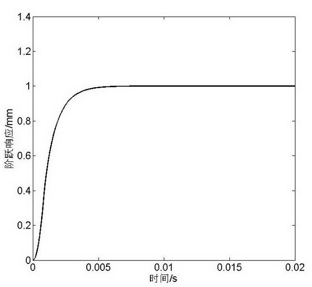
[0045] In this example, the trajectory tracking method proposed by the present invention is used to simulate the mechanism model described in formula 9, and the diamond tool trajectory is a step curve with an amplitude of 1 mm. The selected forgetting factor is 0.99, and the unitary operator in operation 3 for:

[0046] (10)

[0047] The tracking effect is attached image 3 As shown, it can be seen from the figure that the response of the tracking method to the step signal has the advantages of no overshoot and fast response time.

example 2

[0048] Example 2. Step tracking

[0049] In this example, the trajectory tracking method proposed by the present invention is used to simulate the mechanism model described in formula 9, and the diamond tool trajectory is a step curve with an amplitude of 0.25 mm. The selected forgetting factor is 0.99, and the unitary operator in operation 3 As shown in formula 10. The tracking effect is attached Figure 4 It can be seen from the figure that the method of the present invention also has a good tracking effect on the step trajectory.

example 3

[0050] Example 3. Sine tracking

[0051] In this example, the trajectory tracking method proposed by the present invention is used to simulate the mechanism model described in formula 9, and the diamond tool trajectory is a sinusoidal curve with an amplitude of 1 mm and a frequency of 200 Hz. The selected forgetting factor is 0.95, and the unitary operator in operation 3 As shown in formula 10. The tracking error curve is attached Figure 5 As shown, it can be seen from the figure that the steady-state tracking error of the method of the present invention for the sinusoidal trajectory is about 0.25%, which can better realize the high-precision tracking of the diamond trajectory.

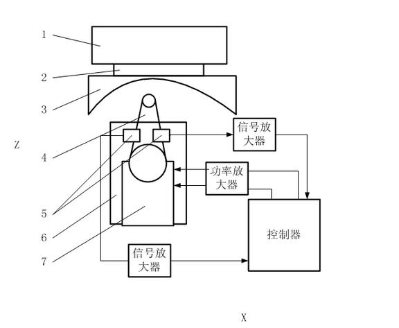
[0052] The system for realizing the method of the present invention is realized through the following technical solutions in specific implementation, combined with the attached figure 1 described as follows:

[0053] The workpiece 3 is clamped on the spindle 1 by the fixture 2 ; the tool 4 and t...


PUM


Abstract

The invention relates to a diamond lathing cutter track tracing method which belongs to the field of micronano processing and ultraprecise processing, in particular to a cutter track tracing method in the diamond lathing process. The diamond lathing cutter track tracing method comprises the following steps of: quantizing a tracing error; obtaining an entangled state quantum error; obtaining a quantum state historical control parameter; obtaining digital control amount; carrying out inner product operation on a quantum bit in a ground state and the quantum state control parameter to obtain a final control amount which is suitable for digital amount control; and acting on a driver of the cutter for finishing tracing on a cutter track. The method provided by the invention is simple, does not need complicated parameter design and selection, has certain generality and is convenient for application and popularization in industrial control.

Description

technical field [0001] The invention belongs to the field of micro-nano machining and ultra-precision machining, and relates to a method for tracking tool tracks in the process of diamond turning. Background technique [0002] Complex surface parts such as optical free-form surfaces and bionic microstructure surfaces have a wide range of application requirements in many important fields. How to process and manufacture curved surface parts with complex geometric features and high-quality requirements has become one of the keys to drive the development of these fields. Single-edge diamond turning is considered to be an ultra-precision machining method that can efficiently obtain complex surface topography and high surface processing quality. On this basis, diamond turning, diamond flying cutting, and elliptical vibration cutting based on fast tool servo have been developed. And other different processing methods have very good development prospects, and have received extensive...

Claims


Application Information

Patent Timeline
Patent Type & Authority Applications(China)
IPC IPC(8): G05B19/19
CPCY02P90/02
Inventor 周晓勤朱志伟林洁琼
Owner HUAWEI TEHCHNOLOGIES CO LTD
Why Eureka
Try Eureka