Antireflection film, polarizing plate and image display device

a technology of anti-reflection film and polarizing plate, which is applied in the direction of polarizing elements, instruments, other domestic objects, etc., can solve the problems of low scratch resistance, low scratch resistance, and difficulty in realizing a low refractive index and a high scratch resistance at the same time, so as to improve the scratch resistance and high anti-reflection property

Inactive Publication Date: 2008-05-13
FUJIFILM CORP
View PDF21 Cites 29 Cited by
  • Summary
  • Abstract
  • Description
  • Claims
  • Application Information

AI Technical Summary

Benefits of technology

[0008]An object of the present invention is to provide an antireflection film improved in the scratch resistance while keeping sufficiently high antireflection property. The object of the present invention includes providing a polarizing plate and a display device using this antireflection film.
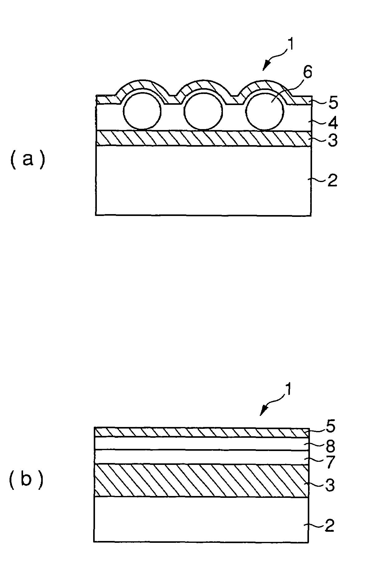
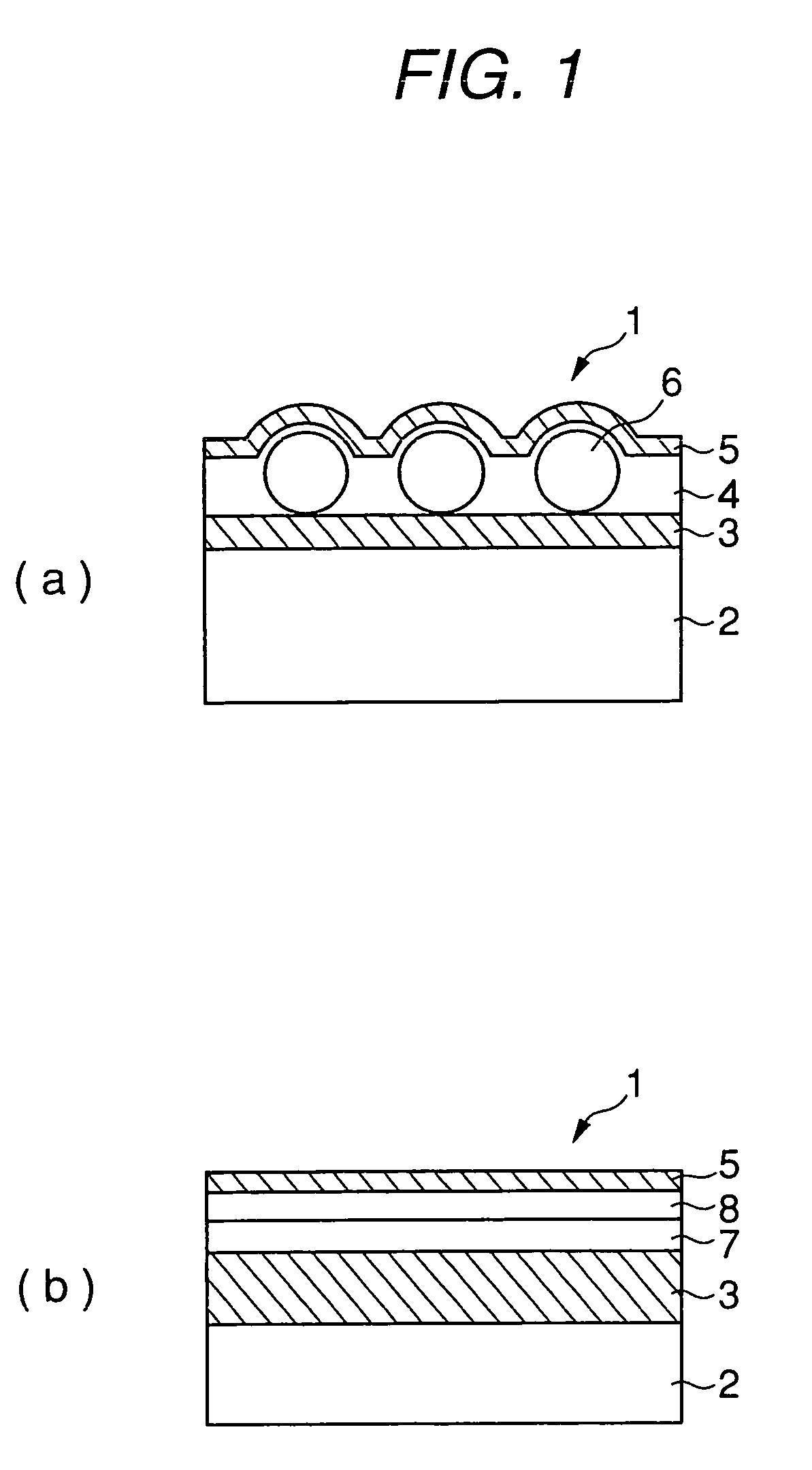
[0009]As a result of extensive investigations, the present inventors have found that when at least one inorganic particle having a particle size responding to the thickness of a low refractive index layer comprising a fluorine-containing polymer is used in the low refractive index layer, the film strength can be remarkably improved while suppressing the increase in the refractive index of the layer itself and moreover, this is not bound to restrictions of long-term heat curing or saponification treatment.

Problems solved by technology

For lowering the refractive index of a material, techniques of (1) introducing a fluorine atom and (2) decreasing the density (introducing voids) may be used, however, in both of these techniques, the film strength or the adhesive property at the interface is liable to decrease and low scratch resistance results.
Thus, it has been difficult to realize a low refractive index and a high scratch resistance at the same time.
As described in JP-A-2002-265866 (the term “JP-A” as used herein means an “unexamined published Japanese patent application”) and JP-A-2002-317152, the film strength may be increased to a certain extent by a method of using a fluorine-containing sol-gel film, however, this method causes large restrictions, for example, (1) curing requires heating over a long time and the load of production is large or (2) the film has no resistance against a saponification solution (alkali treatment solution) and in the case of saponifying the TAC surface, this treatment cannot be performed after the antireflection film is formed.
This technique is effective to a certain extent for the improvement of scratch resistance, however, in the case of a film lacking in the substantial film strength and interface adhesion, a sufficiently high scratch resistance cannot be obtained only by this technique.

Method used


Image

  • Antireflection film, polarizing plate and image display device
  • Antireflection film, polarizing plate and image display device
  • Antireflection film, polarizing plate and image display device

Examples


example 1

(1) Formation of Antiglare Hard Coat Layer

[0364]A 80 μm-thick triacetyl cellulose film (TAC-TD80UL, produced by Fuji Photo Film Co., Ltd.) in a roll form was unrolled and thereon, Coating Solution A for antiglare hard coat layer prepared above was coated using a doctor blade and a microgravure roll having a diameter of 50 mm and having a gravure pattern with a line number of 180 lines / inch and a depth of 40 μm, at a gravure roll rotation number of 30 rpm and a transportation speed of 10 m / min. Thereafter, the coating solution was dried at 60° C. for 150 seconds and then an ultraviolet ray was irradiated thereon at an illuminance of 400 mW / cm2 and a dose of 250 mJ / cm2 using an air cooled metal halide lamp of 160 W / cm (manufactured by I-Graphics K.K.) under nitrogen purging to cure the coating layer and thereby form an antiglare hard coat layer having a thickness of 4.3 μm. Then, the film was taken up.

(2) Formation of Low Refractive Index Layer

[0365]The triacetyl cellulose film having...

example 2

(Preparation of Coating Solution for Hard Coat Layer)

[0416]To 315.0 g of a dipentaerythritol pentaacrylate and dipentaerythritol hexaacrylate mixture (DPHA, produced by Nippon Kayaku Co., Ltd.), 450.0 g of a methyl ethyl ketone dispersion solution of silica fine particle (MEK-ST, solid concentration: 30 mass %, produced by Nissan Chemicals Industries, Ltd.), 15.0 g of methyl ethyl ketone, 220.0 g of cyclohexanone and 16.0 g of a photopolymerization initiator (Irgacure 907, produced by Nippon Ciba Geigy) were added and stirred. The resulting solution was filtered through a polypropylene-made filter having a pore size of 0.4 μm to prepare a coating solution for hard coat layer.

(Preparation of Titanium Dioxide Fine Particle Dispersion Solution)

[0417]The titanium dioxide fine particle used was a titanium dioxide fine particle (MPT-129, produced by Ishihara Sangyo Kaisha, Ltd.) containing cobalt and surface-treated by using aluminum hydroxide and zirconium hydroxide.

[0418]To 257.1 g of t...

example 3

[0439]A PVA film was dipped in an aqueous solution containing 2.0 g / liter of iodine and 4.0 g / liter of potassium iodide at 25° C. for 240 seconds and further dipped in an aqueous solution containing 10 g / liter of boric acid at 25° C. for 60 seconds. Subsequently, the film was introduced into a tenter stretching machine in the form shown in FIG. 2 of JP-A-2002-86554 and stretched to 5.3 times. Then, the tenter was bent as shown in FIG. 2 with respect to the stretching direction and thereafter, the width was kept constant. The film was dried in an atmosphere at 80° C. and removed from the tenter. The difference in the conveyance speed between right and left tenter clips was less than 0.05% and the angle made by the center line of film introduced and the center line of film delivered to the next step was 46°. Here, |L1-L2| was 0.7 m, W was 0.7 m and a relationship of |L1-L2|=W was established. The substantial stretching direction Ax-Cx at the tenter outlet was inclined at 45° with resp...


PUM

PropertyMeasurementUnit
refractive indexaaaaaaaaaa
thicknessaaaaaaaaaa
refractive indexaaaaaaaaaa

Abstract

The present invention can provide an antireflection film improved in the scratch resistance while having a sufficiently high antireflection property, and a polarizing plate and a display device using the antireflection film, the antireflection film antireflection film comprising: a transparent support; and as an outermost layer, a low refractive index layer containing a fluorine-containing polymer, wherein the low refractive index layer comprises at least one inorganic fine particle having an average particle size of 30 to 100% of the thickness of the low refractive index layer; the polarizing plate using the antireflection film for one of two protective films of a polarizer in the polarizing plate; and the image display device using the antireflection film or polarizing plate for the outermost surface of the display.

Description

[0001]This application is a 371 of PCT / JP03 / 10359, filed Aug. 14, 2003.TECHNICAL FIELD[0002]The present invention relates to an antireflection film, and a polarizing plate and an image display device using the antireflection film.BACKGROUND ART[0003]On a display device such as cathode ray tube display device (CRT), plasma display panel (PDP), electro-luminescence display (ELD) and liquid crystal display device (LCD), the antireflection film is generally disposed on the outermost surface of the display so as to prevent the reduction in contrast due to reflection of external light or prevent entering of an image by reflection.[0004]In general, such an antireflection film is produced by forming a low refractive index layer to an appropriate thickness on a support, in which the refractive index of the low refractive index layer is lower than that of the support. In order to realize a low reflectance, a material having a refractive index as low as possible is preferably used for the low ...

Claims


Application Information

Patent Timeline
Patent Type & Authority Patents(United States)
IPC IPC(8): G02B1/11B32B27/00G02B5/02B32B27/08B32B27/30G02B5/30G02F1/1335G02F1/13363
CPCB32B27/08G02B1/111Y10T428/10Y10T428/25Y10T428/1014Y10T428/1036Y10T428/1041Y10T428/259C09K2323/023C09K2323/031C09K2323/03C09K2323/00G02B1/115G02B5/3025B32B2307/7265B32B2307/412B32B27/18B32B27/28B32B7/12B32B2457/202B32B2307/21B32B2307/42
Inventor MATSUNAGA, NAOHIROIBUKI, SHUNTARO
Owner FUJIFILM CORP
Why Eureka
Try Eureka