[0010]Another
advantage of the present invention is that a
scintillation based radiation detector can be optically coupled with one or more position-sensitive photodetectors for
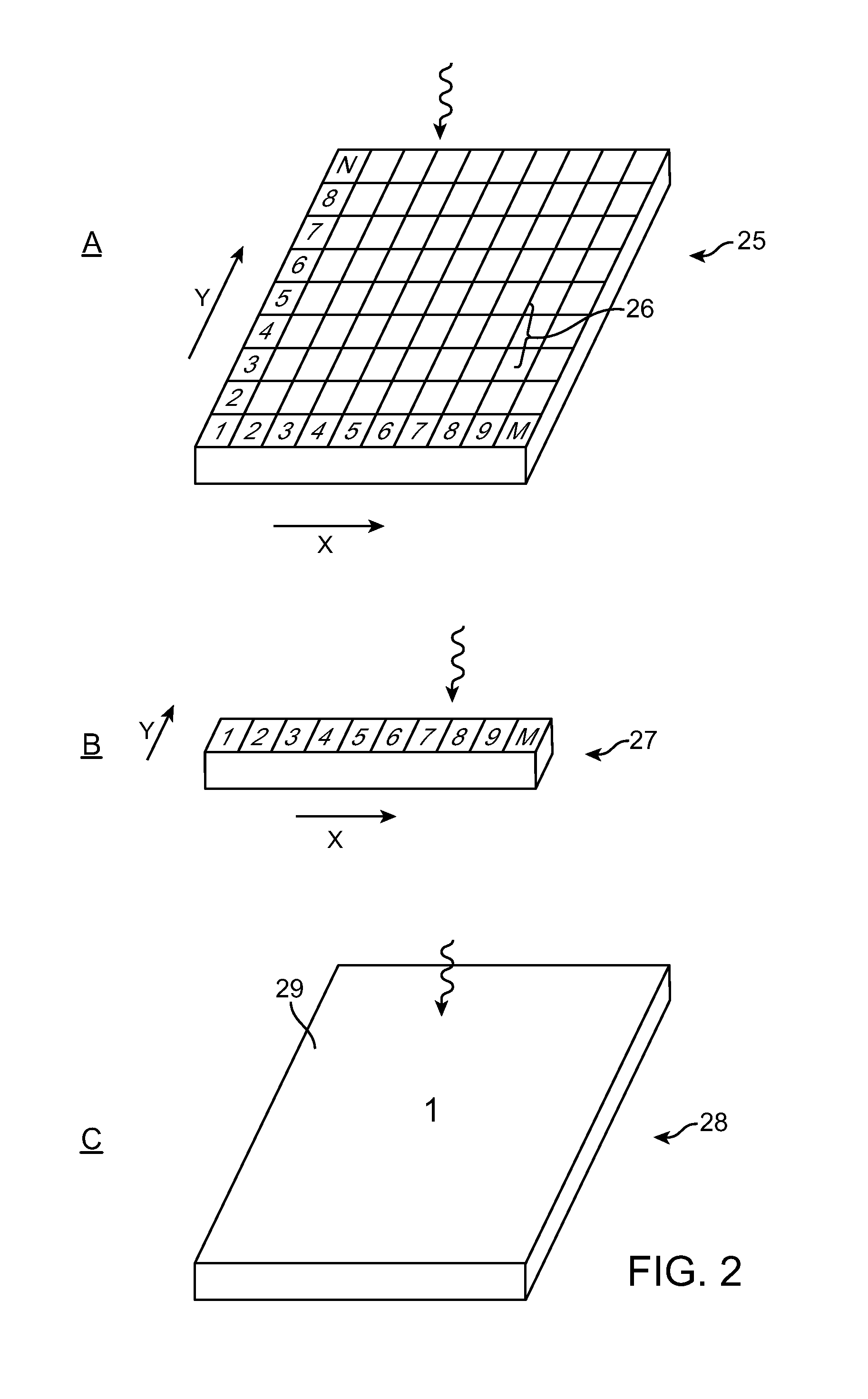
improved performance radiation detection and imaging assemblies. A position-sensitive photodetector is capable of determining the position on the photodetector at which an interaction with an incident light
photon occurs. The determination can be made in either one dimension (“one-dimensional” photodetector, also called a linear or
linear array photodetector) or two dimensions (“two-dimensional” photodetector). Two-dimensional photodetectors are capable of localizing where in a two-dimensional detection plane a light
photon has interacted with the photodetector. One-dimensional photodetectors can locate a point of interaction of light along one axis, rather than two. The
light detection from multiple sides of a
scintillation detector together with
optical coupling of one or more position-sensitive photodetectors, rather than
single element detectors that are not position sensitive, allows for significantly
improved performance imaging. For example, the assemblies of the present invention allow for both one-dimensional and two-dimensional imaging based on
light detection from multiple sides of the radiation detector, as well as permits
point source imaging in one dimension at a
high count rate (large
radiation flux), and performance of one-dimensional and two-dimensional
distributed source imaging at high count rates (large
radiation flux). As used herein, the terms “low count rate” and “low
radiation flux” are generally used interchangeably and refer to a
particle interaction rate in the scintillator such that the average interval between consecutive interactions in the scintillator is no larger than a fraction of the resolving time of the photodetector
electronics. For instance, if the photodetector is read out at a rate of 1 sample / msec, then a count rate of 600 interactions / sec is considered a low count rate, and 2,000 interactions / sec is considered a
high count rate. In medical x-
ray imaging, x-
ray interaction rates in the scintillator can easily exceed 1,000,000 interactions / sec, and for these applications the same photodetector with a 1 msec sampling time has to be capable of handling high count rates.
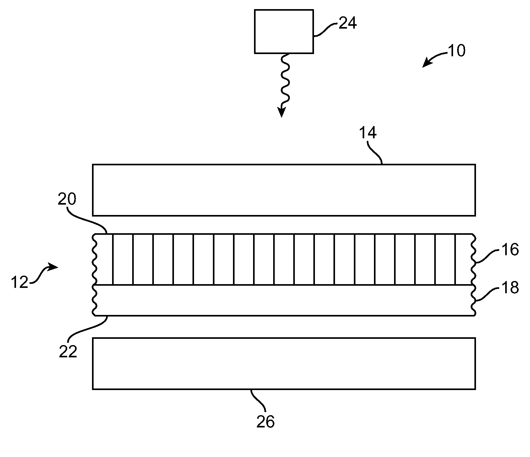
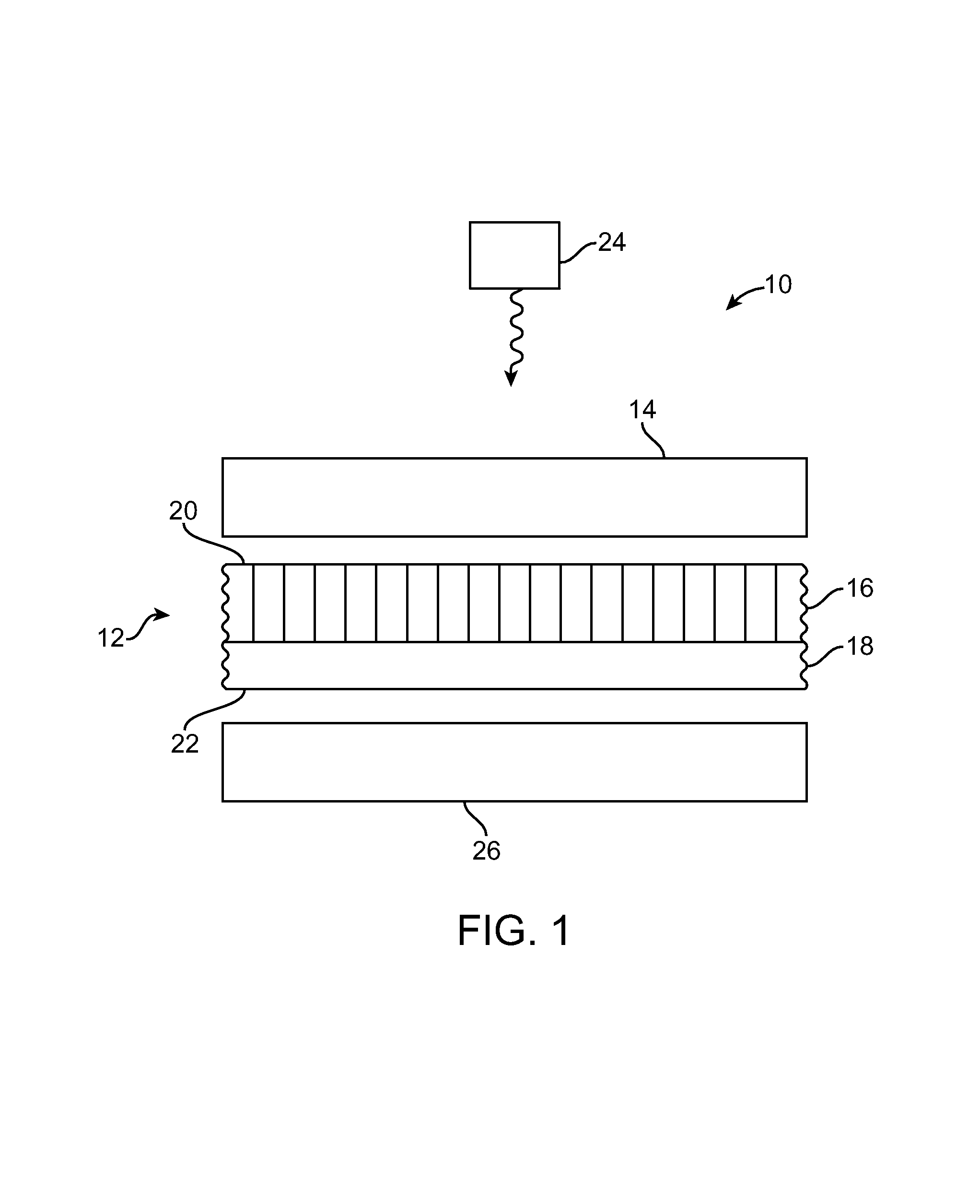
[0011]Thus, in one aspect of the present invention, a radiation detection
assembly is provided. The
assembly includes a radiation detector comprising a scintillator layer and an optically transparent substrate, the detector having a first side and a second side, a first imaging photodetector optically coupled to the first side of the detector, and a second imaging photodetector optically coupled to the second side of the detector, wherein at least one of the photodetectors is a position-sensitive imaging photodetector.
[0012]In another aspect, the present invention provides methods of making a radiation detector. Such a method includes depositing a scintillator layer on an optically transparent substrate so as to produce a detector having at least a first side and a second side. The method further includes optically
coupling the first side of the detector to a first imaging photodetector, and optically
coupling the second side of the detector to a second imaging photodetector. At least one of the photodetectors is a position-sensitive imaging photodetector.
[0013]In another aspect, a method of making a position-sensitive radiation detection device is provided. The method includes producing a flexible scintillator detector by forming a first
resin coating on a substrate, depositing a scintillator layer on the first
resin coating, and removing from the substrate the combination of the first
resin coating and the scintillator, thereby producing a flexible scintillator comprising a first resin
coating and scintillator layer. Optionally, a second resin
coating can be deposited on the surfaces of the scintillator not in contact with the first resin
coating, which can provide a complete cover of the scintillator. The method additionally includes optically
coupling a first side of the flexible scintillator detector to a first imaging photodetector, and optically coupling a second side of the flexible scintillator detector to a second imaging photodetector, wherein at least one of the photodetectors is a position-sensitive photodetector.
[0014]A radiation detector of the invention
assembly can include a variety of optically transparent substrates. In one embodiment, the substrate includes compositions such as a glass, plastic, or resin. In another embodiment, the substrate includes a
fiber optic plate,
prism, lens, or scintillator. The substrate can be a detector device or portion or surface thereof (e.g., optical assembly, photodetector, etc.). The substrate can be separate from a detector device and / or comprise a detector portion (e.g., scintillator panel) that can be adapted to or incorporated into a detection device or assembly.
[0015]In another embodiment of the present invention, a radiation detector of the assembly includes a resin layer or coating. A resin coating typically includes an
organic polymer, for example, such as para-
xylylene polymer compositions. Resin coatings can also include films, tapes, and the like and can comprise materials such as polyesters (e.g., Mylar), polyimides (e.g.,
Kapton™), polyvinylidene chlorides (e.g., saran resins or films), and
epoxy polymers. Thus, in one embodiment, the radiation detector includes a substrate, a scintillator layer, and a resin coating disposed between the optically transparent substrate and the scintillator. For example, the radiation detector can include a resin coating or layer formed on a substrate and a scintillator layer deposited on the resin coating. In some instances, a resin coating comprises the optically transparent substrate. For example, a resin coating can be formed on a substrate and a scintillator layer then deposited on the resin coating. Following deposition of the scintillator layer on the resin, the combination of the resin coating and scintillator layer can be removed from the substrate so as to form a “flexible” scintillator detector, comprising a scintillator layer and optically transparent resin layer. Thus, in another aspect, the present invention provides a flexible radiation detector. The flexible radiation detector comprises a first resin layer and a scintillator layer deposited on the first resin layer. Without a substantially rigid component, such as the substrate on which it is initially formed, the flexible radiation detector is capable of being bent or flexed without damage (e.g., breaking apart, flaking, etc.) to the scintillator layer.

