Hydraulic liquid pumping system

a pumping system and hydraulic technology, applied in the direction of liquid degasification, fluid coupling, separation process, etc., can solve the problem of limited area in which many hydraulic air compressor systems could be located

Active Publication Date: 2008-05-27
A BETTER POWER
View PDF50 Cites 31 Cited by
  • Summary
  • Abstract
  • Description
  • Claims
  • Application Information

AI Technical Summary

Problems solved by technology

These geographic constraints drastically limited the areas that many hydraulic air compressor systems could be located.
Furthermore, water passing through a traditional liquid pumping system could be used only once, thereby requiring a continuous renewable resource of liquid to drive the system.

Method used


Image

  • Hydraulic liquid pumping system
  • Hydraulic liquid pumping system
  • Hydraulic liquid pumping system

Examples


example 1

[0052]A partial system set-up was constructed to demonstrate that a relatively low air pressure can be used to pump water in a system as described above at a rate sufficient to sustain the water-air hydraulic cycle. With the proper height ratio of down pipe height to discharge pipe height the system can return liquid to the starting point within the system.

[0053]A first rack was positioned 234″ above the ground and a source liquid area tank having a 175-gallon volume was positioned on the first rack. The sides of the source liquid area tank were 14″ high. Water was fed from the source liquid area tank into a funnel at the top of a down pipe comprising a 3″ length of 4″ diameter pipe connected to a 4″ length of 3″ diameter pipe connected to an 8″ length of 2″ diameter pipe connected to a 1.5″ diameter plastic pipe having a length of 209″. The total length of the down pipe was 224″. Water was introduced to the funnel by a 2″ right angle pipe connected to a 1.375″ butterfly valve exten...

example 2

[0059]The second trial was made using the system of Example 1 with several modifications. A clear plastic 2″ diameter pipe was attached below the funnel. Inside the 2″ pipe a 1″ gas entrainment pipe with 0.125″ holes drilled into the sides was inserted. The gas entrainment pipe was used to supply air to the stream of water traveling down the down pipe. The 1″ plastic pipe had a 1.25″ outer diameter and the area difference between the 2″ inner diameter down pipe and the 1.25 outer diameter gas entrainment pipe was 1.914 in2. This was slightly bigger than the area of a 1.5″ inner diameter pipe (1.76 in2). For this evaluation, the areas of the two pipes when joined were considered equivalent. The 1″ pipe extended into the 2″ clear plastic pipe a length of 10 feet. The 1″ pipe extended upwards such that the 1″ pipe stuck out three feet above the funnel entrance and above the water level of the liquid source area tank. This was constructed to prevent water, seeking its own level, from co...

example 3

[0061]The third trial was made using the system of Example 2 with several modifications. The water height of the down pipe was increased by removing the funnel and the 1″ air pipe and connecting the down pipe to the liquid source area tank by a 90° 2″ fitting. This raised the water fall level to 242″ or 20.33 ft. This arrangement eliminated any air entrapment in the down pipe until the air was injected at the 212″ level down from the liquid source area tank. With this arrangement, the water flow is maximized since there is no air in the water prior to the introduction of the air entrainment pipe. At the 17.67 ft depth, the water pressure was measured at 7.65 psi.

[0062]Two air injectors were constructed to inject air into the falling water stream. The two injectors were made of ⅜″ copper tubing. One tube section was drilled with thirteen 1 / 16″ holes along a 6″ distance. The second tube section was made from a similar copper pipe but was cut at a 60° angle to the vertical, to expose a...


PUM

PropertyMeasurementUnit
heightaaaaaaaaaa
heightaaaaaaaaaa
heightaaaaaaaaaa

Abstract

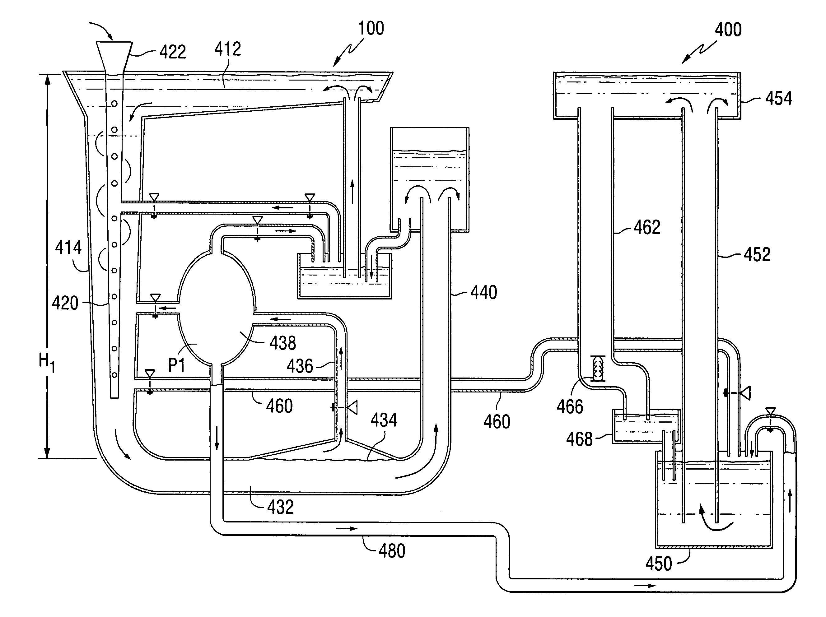
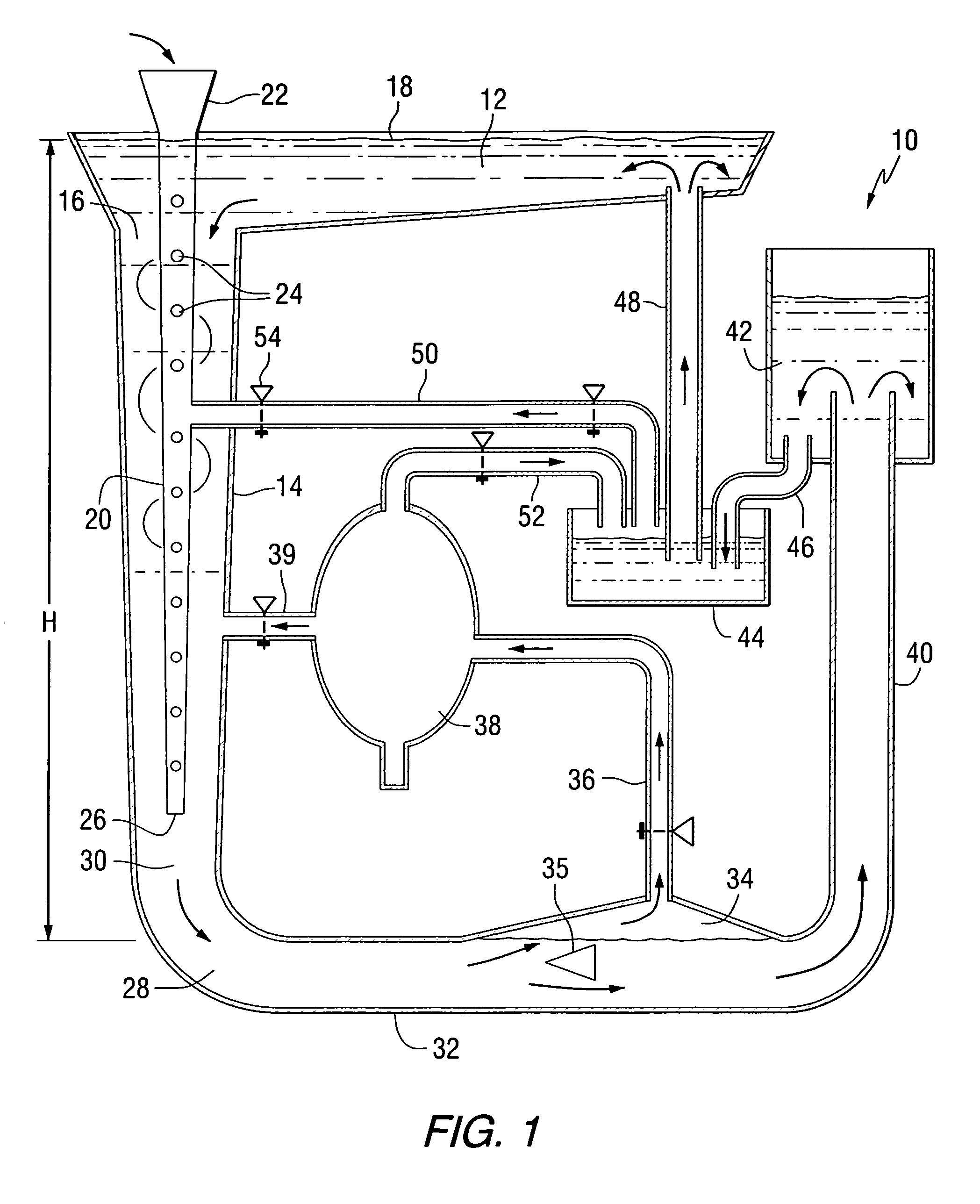
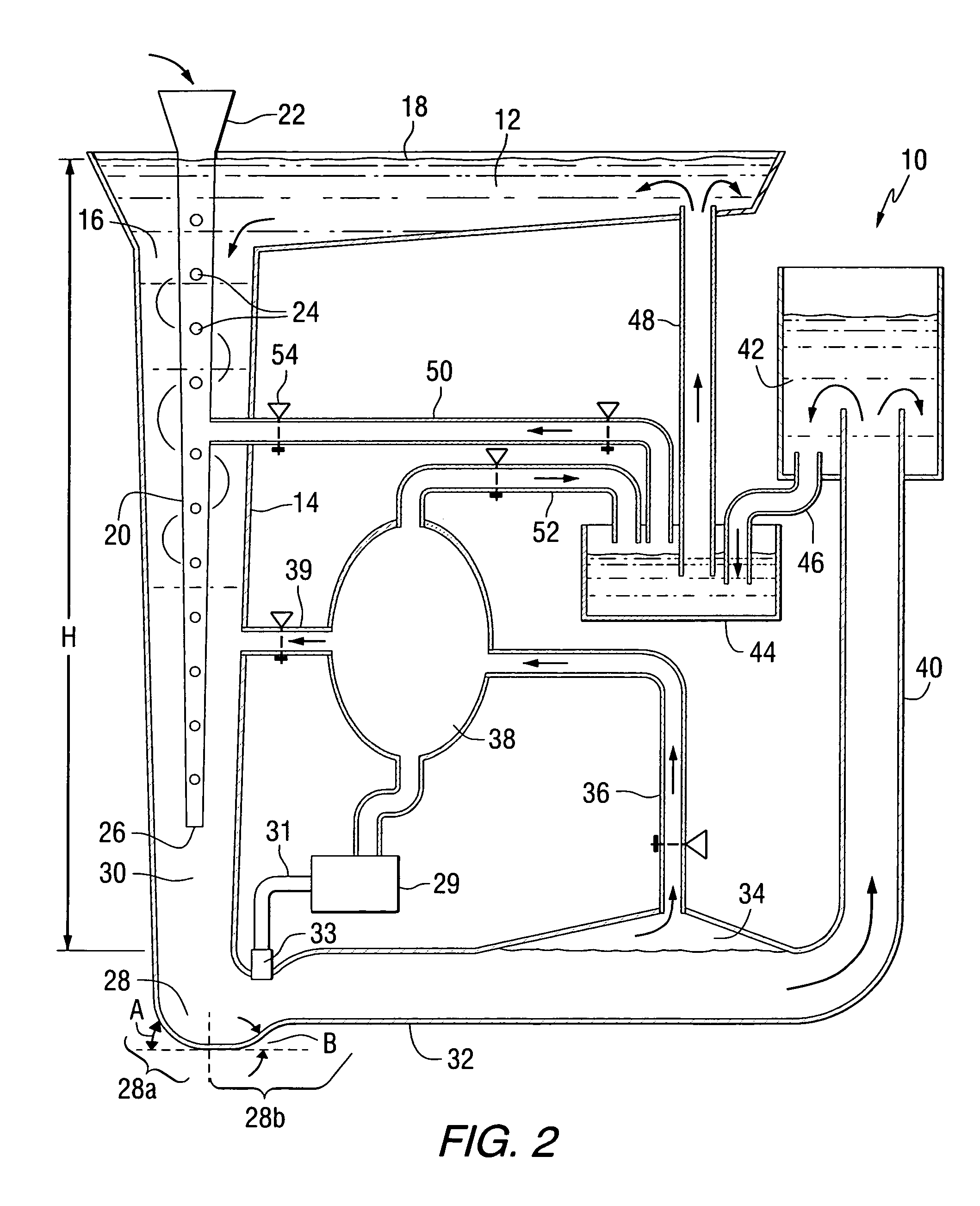
A system for concentrating gas, using the concentrated gas to pump liquid, and recycling the gas and liquid is disclosed. The system comprises a body of liquid, a down pipe in fluid communication with the body of liquid, a gas injection apparatus for introducing gas into the liquid that passes through the down pipe, a separator for separating compressed gas from the liquid, and a gas-liquid recycle loop. The down pipe and the gas injection apparatus are structured and arranged to compress the gas. The gas-liquid recycle loop comprises a compressed gas storage vessel containing the separated gas, a reservoir containing liquid separated from the compressed gas, and a gas-liquid pump. The gas-liquid pump has a gas inlet in communication with the gas storage vessel, and a fluid inlet in communication with the reservoir. The gas-liquid pump is structured and arranged for pumping the liquid back to the body of liquid and delivering the gas to the gas injection apparatus. A turbine in fluid communication with the liquid that passes through the down pipe can be optionally included. A second loop system comprising a second body of liquid, a second down pipe in fluid communication with the second body of liquid, and a second gas-liquid pump is also disclosed. The second gas-liquid pump comprises a second gas inlet in communication with a compressed gas storage area, a second liquid inlet in communication with the second liquid that passes through the second down pipe, the second gas liquid pump structured and arranged for pumping the second liquid to the second body of liquid. A second turbine in fluid communication with the liquid that passes through the second down pipe can optionally be included.

Description

CROSS REFERENCE TO RELATED APPLICATIONS[0001]This application claims the benefit of U.S. Provisional Application No. 60 / 600,500 filed Aug. 11, 2004, which is incorporated herein by reference.FIELD OF THE INVENTION[0002]The present invention relates to a liquid pumping system, and more particularly to a liquid pumping system that utilizes liquid to compress a gas and uses a part of the compressed gas to recycle the liquid within the system.BACKGROUND INFORMATION[0003]Many liquid pumping systems have means for entrapping and compressing air in order to generate rotational mechanical energy. However, most traditional designs required a naturally occurring steep vertical fall that is fed by a stream of water, such as a waterfall, in order to be operational. This required that the water source must be located on ground having a high altitude and the compressed gas accumulator must be located on ground having a lower altitude. In conventional systems, water expelled from the system is ret...

Claims


Application Information

Patent Timeline
Patent Type & Authority Patents(United States)
IPC IPC(8): B01F3/04
CPCB01D19/0042F03B13/00F03B17/005F04F1/18F04F10/00F05B2220/60Y02B10/50Y02E10/20Y10S261/75
Inventor VRANA, JULIUS S.TIMMONS, WILLIAM W.WALTERS, DAVID J.
Owner A BETTER POWER
Why Eureka
Try Eureka