Electrical domain mitigation of polarization dependent effects in an optical communications system

a technology electric domains, applied in the field of electric domain compensation of polarization dependent effects in optical communication systems, can solve the problems of polarization dependent loss, general unpolarized emission noise, and loss of optical communication systems, and achieve cost-effective effects of mitigating the effect of polarization

Active Publication Date: 2008-06-03
CIENA
View PDF36 Cites 54 Cited by
  • Summary
  • Abstract
  • Description
  • Claims
  • Application Information

AI Technical Summary

Benefits of technology

[0022]Accordingly, an object of the present invention is to provide a cost-effective technique for mitigating effects of polarization on high bandwidth optical signals in an optical communications system.
[0023]An aspect of the present invention provides a method of mitigating polarization dependent effects (PDEs) of an optical link of an optical communications system. According to the invention, a compensation function is derived that at least partially compensates the PDEs of the optical link. An input signal is then processed, in the electrical domain, using the compensation function to generate a predistorted signal. With this arrangement, modulation of an optical source using the predistorted signal generates a corresponding predistorted optical signal for transmission through the optical link. As the predistorted optical signal traverses the link, the PDEs of the link operate on the optical signal so that a substantially undistorted optical signal is obtained at a receiving end of the link.
[0025]Thus the method of the invention implements PDE compensation at the transmitter end of the optical link, prior to Electrical-to-Optical (E / O) conversion of the input signal. This arrangement is particularly advantageous, because it enables PDE compensation to be effectively implemented independently of the type of detection (i.e., direct or coherent) used in the receiver.

Problems solved by technology

Optical communications systems suffer degradation attributable to Polarization Dependent Loss (PDL) generally through transients and noise.
Transient changes in the polarization couplings along a fiber route cause a transient change in the received power of a polarized signal, which cause errors in the receiver.
Furthermore, Amplified Spontaneous Emission (ASE) noise is generally unpolarized, and so PDL along an optical fiber route will tend to attenuate the polarized signal more than the ASE noise travelling with that signal.
This will further impair the optical signal-to-noise ratio.
A limitation of this approach is that WDM systems that achieve high spectral efficiencies (e.g., better than about 0.3 bits per second per Hz) generally suffer significant distortion penalties for each multiplexing and demultiplexing function.
Within these deadbands, signals cannot be transmitted and PDL cannot be compensated.
This tightly ties the PDL compensation system to the particular wavelength plan of the communications system, which is undesirable.
While this approach avoids undesirable deadbands, it can only compensate a portion of the PDL within the wavelength band, leaving at least some PDL un-compensated.
However, depolarization does not permit any dynamic equalization of PDL across a spectrum of channels.
Cross-coupling of energy between the polarization modes, in the presence of this differential group delay (DGD), causes waveform distortion and consequent degradation of optical signal quality.
Future optical transmission systems are expected to achieve data transmission rates of 40 Gb / s (or more), and thus are more likely to be limited by the effects of polarization mode dispersion.
These compensation methods typically suffer disadvantages in that the phase delay of controllable birefringent materials typically varies approximately linearly with polarization angle and wavelength.
However, PMD is typically non-linear across the range of wavelengths used in WDM optical transmission systems.
It is therefore difficult to obtain the desired differential phase delay across the wavelength band of interest.
All-optical PMD compensator devices intended to address this problem tend to be highly complex, expensive to manufacture, and suffer from high optical losses.
However, it cannot mitigate the effects of second or higher order PMD, nor can it contend with the combined effects of both PMD and PDL, when both of these are present in significant amounts.
All-electrical PMD-compensation systems are normally limited to linear electrical filtering in a coherent receiver.
These systems suffer the disadvantage that they are limited to coherent receivers.
However, because of their high cost, very few coherent receivers have been installed, and the cost of replacing installed receivers with the high-performance coherent receivers is prohibitive.

Method used


Image

  • Electrical domain mitigation of polarization dependent effects in an optical communications system
  • Electrical domain mitigation of polarization dependent effects in an optical communications system
  • Electrical domain mitigation of polarization dependent effects in an optical communications system

Examples


Embodiment Construction

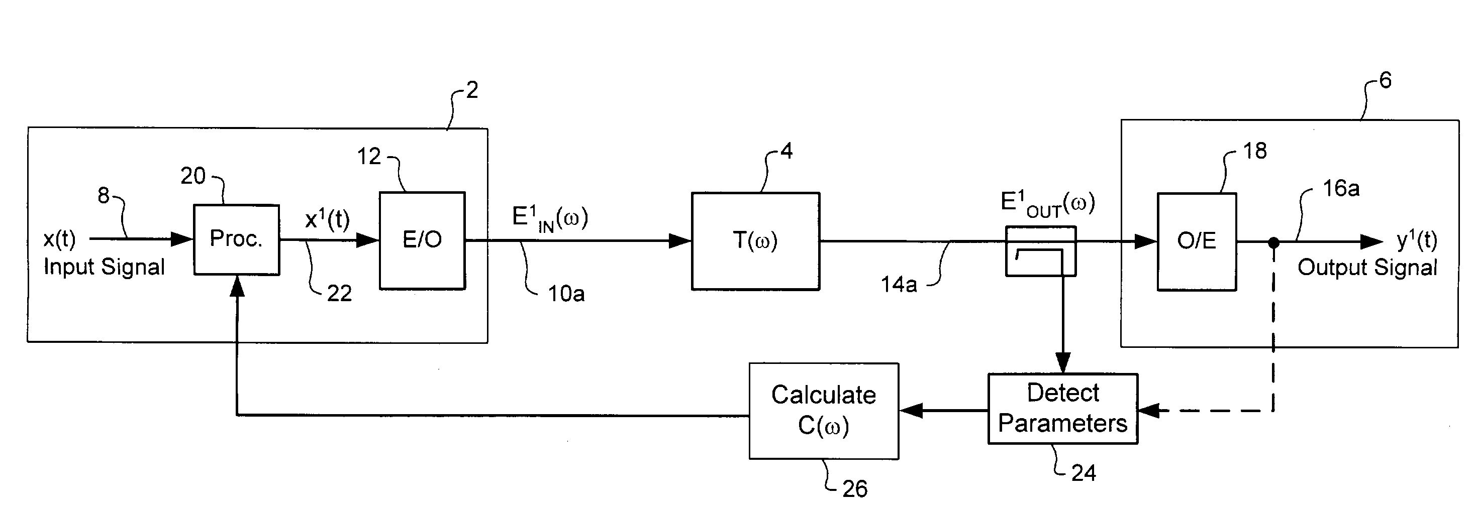
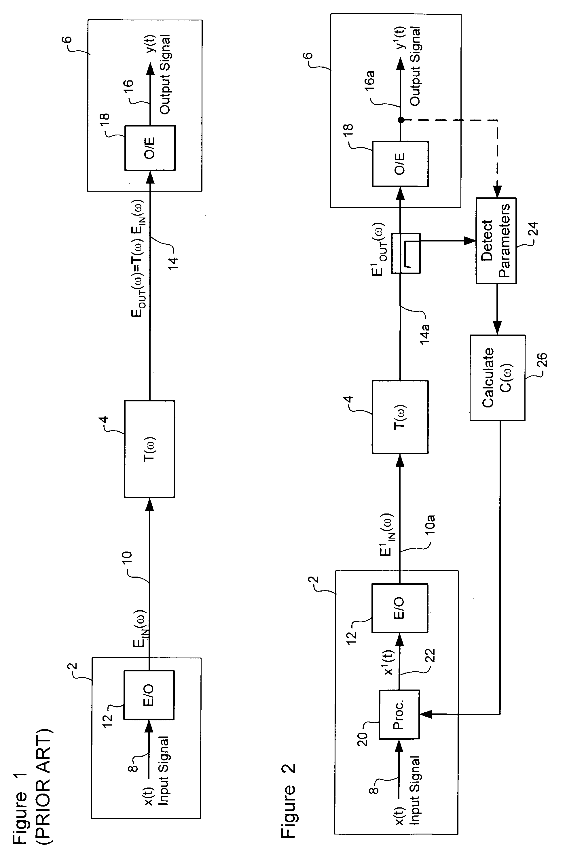
[0034]The present invention provides a method and system for mitigating polarization dependent effects (PDEs), including both polarization mode dispersion (PMD) and polarization dependent loss (PDL), in an optical communications system. FIG. 1 is a block diagram schematically illustrating principal elements of a conventional optical communications system in which the present invention may be deployed. FIG. 2 is a block diagram schematically illustrating principal operations in accordance with the method of the present invention.

[0035]As shown in FIG. 1, an optical communications system is represented by a transmitter 2 and a receiver 6 separated by an optical link 4. As is well known in the art, the link 4 may include multiple optical fiber spans separated by active optical devices such as, for example, optical amplifiers, channel equalizers etc. For simplicity of illustration, these elements are not shown in the drawings. Signal distortions due to Polarization Mode Dispersion (PMD)...


PUM


Abstract

Polarization Dependent Effects (PDEs), including Polarization Mode Dispersion (PMD) and Polarization Dependent Loss (PDL) imposed on optical signals conveyed through an optical link are compensated by processing an input signal in the electrical domain prior to transmission. A compensation function is derived that at least partially compensates the PDEs. The communications signal is then processed in the electrical domain using the compensation function to generate an electrical predistorted signal. The electrical predistorted signal is then used to modulate an optical source to generate a corresponding predistorted optical signal for transmission through the optical link. The PDEs of the optical link operate of the predistorted optical signal such at that substantially undistorted optical signal is received at a receiving end of the link.

Description

CROSS-REFERENCE TO RELATED APPLICATIONS[0001]This is the first application filed for the present invention.MICROFICHE APPENDIX[0002]Not Applicable.TECHNICAL FIELD[0003]The present invention relates to optical communications systems, and in particular to electrical domain compensation of polarization dependent effects in an optical communications system.BACKGROUND OF THE INVENTION[0004]The presence of polarization dependent effects (such as, for example, Polarization Dependent Loss / gain (PDL); Polarization Mode dispersion (PMD); Polarization spectral hole burning; Polarization rotation; nonlinearities that are polarization dependent or that otherwise have a polarization effect; polarization dependent filtering or crosstalk; and Faraday effect) can be a limiting factor in the design of optical transmission systems, particularly those providing long haul transmission at bit-rates of 10 Gb / sec or faster, over optical links (e.g. fibers) of 100 kilometers or more in length. The impact of...

Claims


Application Information

Patent Timeline
Patent Type & Authority Patents(United States)
IPC IPC(8): H04B10/00H04B10/04H04B10/12H04B10/18
CPCH04B10/25137H04B10/2572
Inventor ROBERTS, KIM B.STRAWCZYNSKI, LEOCOMEAU, ADRIENMCNICOL, JOHNO'SULLIVAN, MAURICEPARSONS, KIERAN
Owner CIENA
Why Eureka
Try Eureka