Electric machine for high magnetic reversal frequencies

Inactive Publication Date: 2008-06-10
HILL WOLFGANG
View PDF20 Cites 45 Cited by
  • Summary
  • Abstract
  • Description
  • Claims
  • Application Information

AI Technical Summary

Benefits of technology

[0018]Another significant advantage of the present invention are low losses in the soft magnetic body. Due to the small dimension of the coil perpendicular to the direction of movement short flux paths are generated in relation to the size of the machine or to the air gap surface. The portion of the soft magnetic material on the side of the coils that is facing away from the air gap (yoke area) can be kept small. Thus, electric machines can be realized that have small dimensions in direction to the air gap and can be designed “thin”. A high ratio of the air gap surface to the effective design volume increases power density. Short flux paths and thus a small soft magnetic mass in relation to power lower magnetic losses.
[0019]Additionally, the design permits the utilization of particularly low-loss soft magnetic materials. In one of the embodiments comb-shaped sheet of grain-oriented material is being used. In another embodiment, C-cores of amorphous strip are inserted into the coils from the side facing away from the air gap. At high frequencies, the amorphous material has only a fraction of the losses of crystalline electric sheet machine from a multitude of identical C-cores. The C-cores can consist also of other low-loss soft magnetic strips—e.g. nanocrystalline alloys based on nickel, iron or cobalt. Punching dies are not needed and there is no punching waste. The soft magnetic body is assembled by a pick-and-place machine from a multitude of identical C-cores. The C-cores can consist also of other low-loss soft magnetic strips—e.g. nanocrystalline alloys based on nickel, iron or cobalt.
[0020]In accordance with the invention, the magnetic flux in the secondary part runs also perpendicular to the direction of movement. Independent of the method of the conductor return in the primary part, the power density and efficiency of the machine at like stator volume is improved by an increase in air gap flux density. According to the invention, flux concentration is generated by the arrangement of

Problems solved by technology

Those parts of the coil that are arranged in part or completely perpendicular to

Method used


Image

  • Electric machine for high magnetic reversal frequencies
  • Electric machine for high magnetic reversal frequencies
  • Electric machine for high magnetic reversal frequencies

Examples


Embodiment Construction

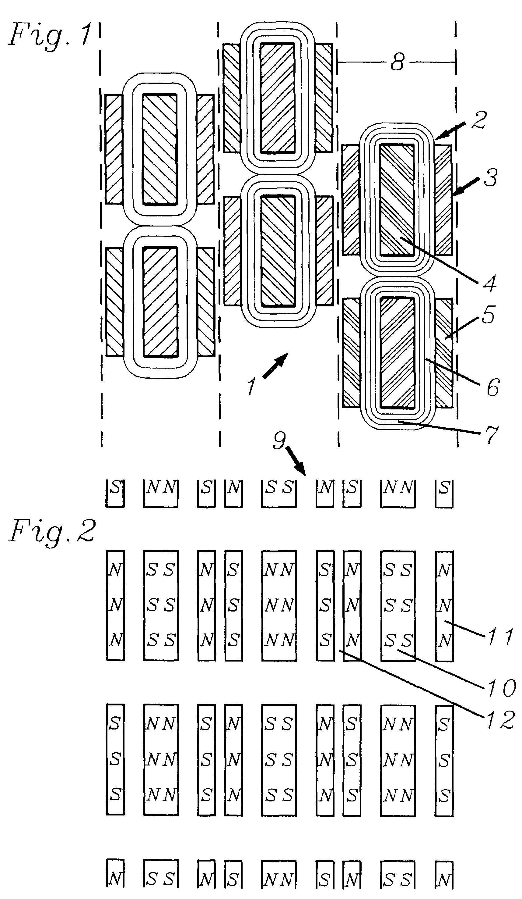
[0049]FIG. 1 shows the construction of the electromagnetically active parts of a primary part (1) in accordance with the invention in a view onto the air gap surface. Six rectangular coils (2), each embedded in E-shaped soft magnetic bodies (3), constitute an electric pole unit which consists of a middle pole (4) and two lateral poles (5). The partial areas (6) of the coils (2) positioned in direction of movement (vertical in the drawing) have a distinctly larger dimension than the partial areas (7) positioned perpendicular to the direction of movement (horizontal in the drawing). Two coils or, respectively, electric pole units arranged sequentially in direction of movement lie in a running track (8) and belong to the same phase. The offset between the three phases is realized in the primary part.

[0050]In FIG. 2 the associated secondary part (9) is shown. Since the phase offset is already being realized in the primary part (1), the magnetic poles (10, 11) of the secondary part form ...


PUM


Abstract

In electric machines, core losses limit, at high fundamental frequency, the permissible full-load power. The aim of the invention is to develop a design which enables a high power density at high magnetic reversal frequencies and which is easy to produce. To this end, the primary part comprises coils which, for the majority of their length, run in the direction of movement and which are surrounded in this area on three sides by soft magnetic material. In the direction of movement, at least two coils are arranged one behind the other. Coils of different phase are arranged perpendicular to the direction of movement inside different running tracks. In the secondary part, at least two oppositely magnetized hard magnets with three collector segments, which are flatly adjacent in a manner that is perpendicular to the direction of movement, form magnet poles having a high flux concentration. The primary and secondary parts can be shifted with regard to one another in a manner that is perpendicular to the direction of movement by means of a mechanism. The machine is characterized by having an easily producible modular design which has low core losses also at high frequencies. A high power density and, at the same time, a large low-loss field control area is realized in compact dimensions.

Description

[0001]This is a continuation of PCT / DE01 / 03373, filed on Aug. 31, 2001 with priority of the German application 100 43 120.8, filed on Aug. 31, 2000, now abandoned.BACKGROUND OF THE INVENTION[0002]1. Field of the Invention[0003]The invention concerns an electric machine with at least one primary part and at least one secondary part, in which the secondary part is moveable in relation to the primary part by the force of magnetic fields.[0004]2. Description of Prior Art[0005]Electric machines with high rpms, or if configured as linear direct drives, with high speeds of movement of primary parts in relation to secondary parts, are characterized by high power densities. In such machines, considerable losses are generated in the soft magnetic body.[0006]If, besides high top speeds, large forces are required, a high peak output (P=v·F) is the result. It is known to reduce this peak output by means of field weakening at high rpms. Induction machines permit a simple realization of field weak...

Claims


Application Information

Patent Timeline
IPC IPC(8): H02K19/00H02K21/00H02K1/06H02K1/27H02K19/02H02K21/14
CPCH02K1/2713H02K1/2766H02K16/00H02K21/14H02K2201/12H02K37/04H02K2213/03
Inventor HILL, WOLFGANG
Owner HILL WOLFGANG
Why Eureka
Try Eureka