System and process for improving engine performance

Inactive Publication Date: 2008-06-24
LEE DENNIS
View PDF19 Cites 7 Cited by
  • Summary
  • Abstract
  • Description
  • Claims
  • Application Information

AI Technical Summary

Benefits of technology

[0009]It is an object of the present invention to maximize the fuel energy efficiency of internal combustion engines while simultaneously minimizing combustion residuals that cause harmful emissions.
[0010]It is another object of the present invention to increase internal combustion engine efficiency by recovering waste heat from the engine cooling system and using that heat to pre-heat the fuel so as to make it more readily combustible.
[0011]It is yet another object of the present invention to further improve the combustibility of the fuel by passing it through an annular array of magnets during the preheating process in order to polarize the fuel, thereby weakening its covalent bonds and rendering the fuel more readily combustible.
[0013]It is yet a further object of the present invention to introduce an acetone-based additive to the fuel in a vehicle's fuel tank, with the additive being so formulated and so proportioned to the fuel as to render the fuel more tractable to the pre-heating, polarization and plasma injection processes.
[0018]The fuel additive stage is implemented by introducing an acetone-based fuel additive directly into a vehicle's tank. By reducing the surface tension of the liquid fuel, the acetone in the additive enables the fuel to atomize into finer droplets and to vaporize more readily. Inclusion of xylene in the additive works to weaken the covalent hydrocarbon bonds of the fuel. Thus the fuel is pre-conditioned and rendered more tractable to the subsequent preheating and polarization stage.
[0019]In the preferred embodiment of the present invention, the fuel additive comprises equal volumes of three constituents: acetone, xylene and a conditioning lubricant. The xylene boosts the fuel's octane rating and thus improves engine performance. The conditioning lubricant, which serves to protect the engine and further condition the fuel, comprises, by volume: one part Accelerator™ octane booster; one part Energy Release™ cylinder coating; three parts GP-7 two-cycle auto racing oil, and three parts Lucas™ auto racing oil. The additive is mixed with fuel in the vehicle's fuel tank at a ratio of 3 fluid ounces of additive to 10 gallons of fuel.

Problems solved by technology

In the prior art electrolysis devices, however, no effort is made to retain the ionized state of the generated gases, which simply revert to molecular hydrogen H2 and oxygen O2.
Consequently, these devices fail to take advantage of the superior combustion characteristics of an ionized hydrogen-oxygen mixture.

Method used


Image

  • System and process for improving engine performance
  • System and process for improving engine performance
  • System and process for improving engine performance

Examples


Embodiment Construction

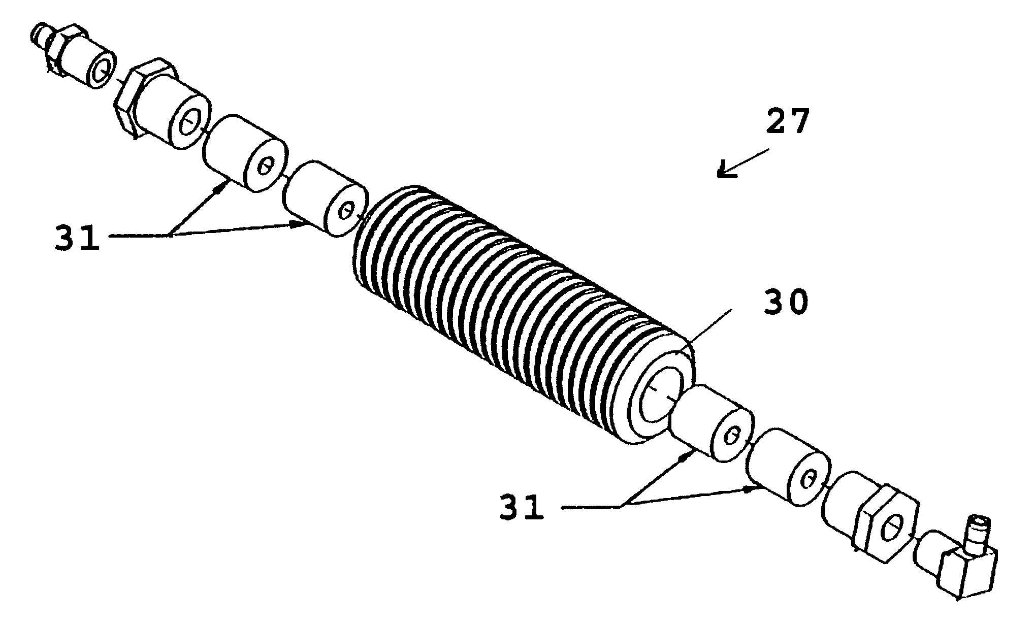
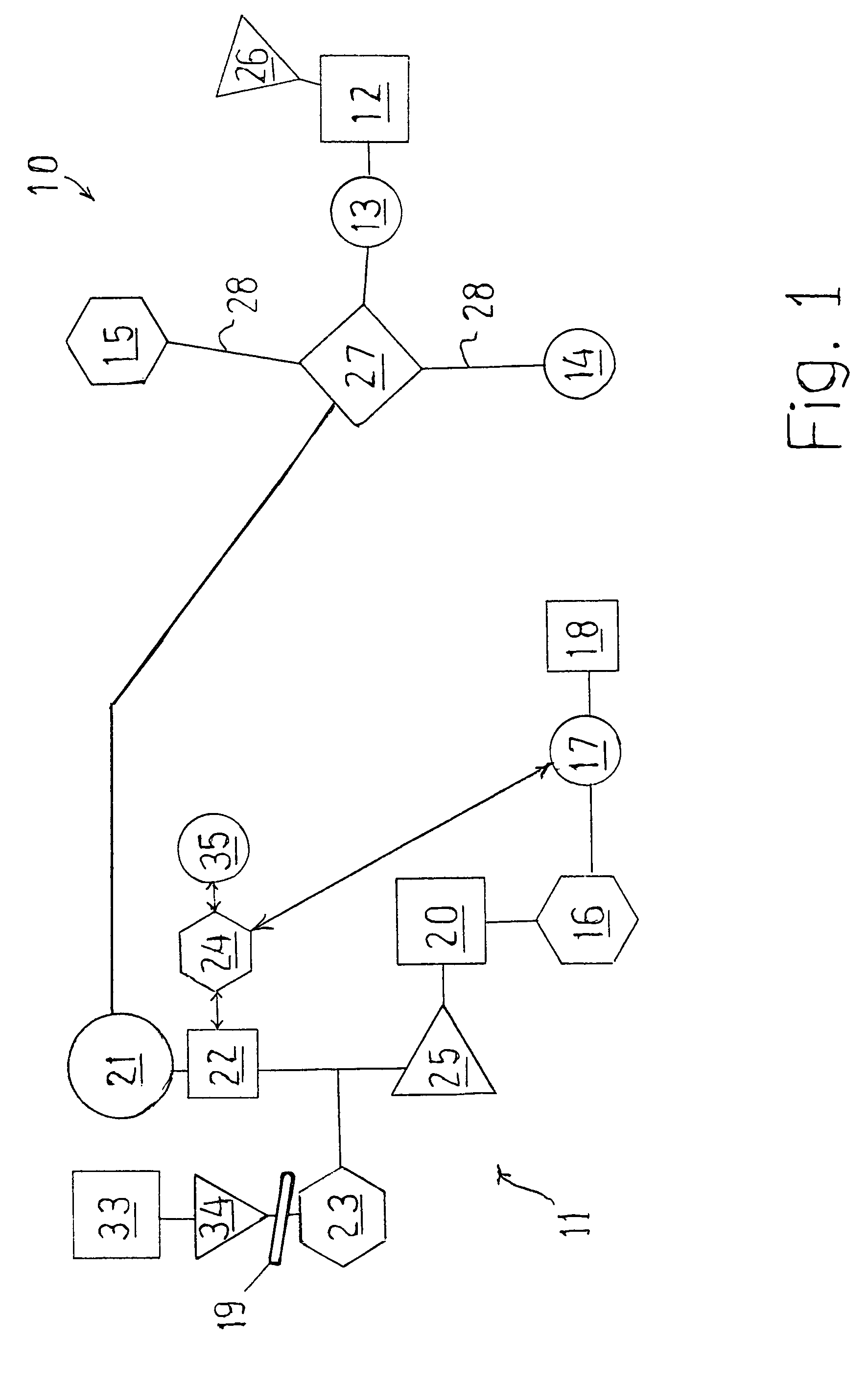
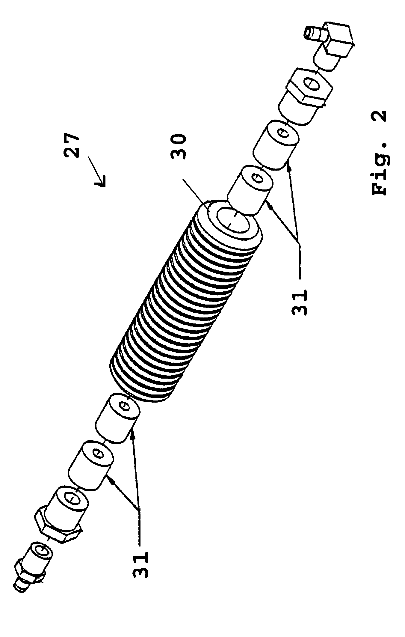
[0026]Referring to FIG. 1, the preferred embodiment of the present invention 10 is designed to be implemented and installed in a motor vehicle having an internal combustion engine 11, a fuel tank 12, a fuel pump 13, a water pump 14, a radiator 15, an exhaust manifold 16, one or more engine / emissions sensors 17, and a catalytic converter 18. Comprising the engine 11 are a throttle plate 19, a plurality of cylinders 20, a plurality of fuel injectors 21, a plurality of injection ports 22, an intake manifold 23, and an engine control module (ECM) 24.

[0027]In the conventional functioning of the engine 11, fuel from the fuel tank 12 is pumped by the fuel pump 13 to the fuel injectors 21. The fuel injectors 21 atomize the fuel and periodically dispense it in discrete pulses through the injection ports 22 into an airflow that enters the engine through the intake manifold 23 under the regulation of the throttle plate 19. The resulting air-fuel mixture is then drawn into multiple intake valve...


PUM


Abstract

An integrated system and process for improving internal combustion engine performance consists of four components: (1) an acetone-based fuel additive phase, (2) a fuel pre-heating and polarization phase, (3) an ionized hydrogen-oxygen plasma injection phase, and (4) a microprocessor-ECM interface phase to optimize the combined performance of the other three components.

Description

BACKGROUND OF THE INVENTION[0001]This invention relates to an integrated system and process for improving the performance of internal combustion engines. Combustion efficiency is increased and exhaust emissions are reduced by the combined effects of: (1) introducing an acetone-based fuel additive in the fuel tank. (2) pre-heating and polarizing the fuel, and (3) mixing a plasma of ionized hydrogen and oxygen with the intake air. This integrated system and process produces synergistic fuel additives with superior combustion characteristics.[0002]With respect to the first component of the present invention, the use of acetone-based fuel additives to improve fuel efficiency is known in the prior art. One example of such a fuel additive is disclosed in Smith, U.S. Pat. No. 6,123,742. Acetone acts as a surfactant with respect to gasoline, reducing the surface tension of the liquid fuel so that it forms finer droplets that vaporize more readily. In the Smith patent disclosure, as in the p...

Claims


Application Information

Patent Timeline
IPC IPC(8): C10L1/00
CPCC10L1/14C10L10/10F02M25/12F02M31/10C10L1/1608C10L1/1616C10L1/1857Y02T10/121Y02T10/126Y02T10/12
Inventor LEE, DENNIS
Owner LEE DENNIS
Why Eureka
Try Eureka