Method and system for power factor correction using constant pulse proportional current

Inactive Publication Date: 2008-06-24
PF1
View PDF32 Cites 104 Cited by
  • Summary
  • Abstract
  • Description
  • Claims
  • Application Information

AI Technical Summary

Benefits of technology

[0039]Accordingly, the present invention is a “non-multiplier” Low Cost High Performances Power Factor Correction Circuit, including novel methods,

Problems solved by technology

Usually, the performances of these kinds of “Passive PFC Solutions” are relatively low, just near the “acceptable” limits of the industry standards.
Unfortunately, being designed as a current mode PWM controller, the existing 384×IC controllers series reaches, in voltage mode of operations (via Q1, as voltage ramp driver) a minimum Output pulse ON time

Method used


Image

  • Method and system for power factor correction using constant pulse proportional current
  • Method and system for power factor correction using constant pulse proportional current
  • Method and system for power factor correction using constant pulse proportional current

Examples


Example

General Description

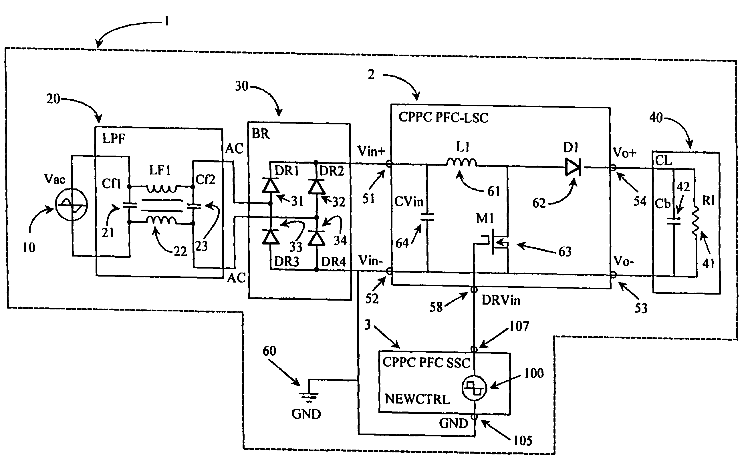
[0070]FIG. 3 illustrates, in accordance with the present invention, a Low Cost High Performance Power Factor Correction System—LCHPPFCS (1), comprising a Power Factor Correction Large Signal Circuit CPPC PFC-LSC (2) and a CPPC Power Factor Correction Small Signal Circuit PFC-SSC (3).

[0071]The LCHPPFCS (1) comprises, typically an alternating current Voltage generator Vac (10), a Low (frequency) Pass Filter block LPF (20), a Bridge Rectifier block BR, (30) a Complex Load block CL (40), and a boost Constant Pulse Proportional Current Power Factor Correction Large Signal Circuit block CPPC PFC-LSC (2).

[0072]The CPPC PFC-SSC (3) comprises, typically a Constant Pulse Proportional Current Controller Circuit CPPC CC and a Controller Related Circuit, however in this specific embodiment, it consists of just a “Constant (frequency, duty cycle and amplitude) Pulse” square wave generator (100). For the remainder of this description the particularly sub circuit presented as CPP...


PUM


Abstract

A Power Factor Correction (PFC) system providing near unity power factor for an AC power source (VAC) connected to a complex load. The system includes a bridge rectifier, boost or buck-boost converter, complex load, and pulse width modulation (PWM) controller to provide pulses with variable duty cycle to a power switch. The invention is a constant pulse proportional current (CPPC) PWM controller that generates trains of pulses constant in frequency and duty cycle for one semi-cycle of the VAC. The duty cycle of the driving signal is modified by applying open-loop correction signals to summing nodes of PWM circuits. Since the PWM provides a constant train of driving pulses with constant duty cycle for one semi-cycle of the VAC, the current absorbed by the converter is contingent and linearly proportional to the voltage. Thus, the output current follows the voltage resulting in a power factor of near unity.

Description

BACKGROUND OF THE INVENTION[0001]1. Field of the Invention[0002]The present invention relates to a Power Factor Correction (PFC) Circuit. More particularly, the present invention relates to a new way of managing and controlling an Active PFC System, not by using a classic “Multiplier” concept and its related circuit, but by using an original “Constant Pulse—Proportional Current” (CPPC) conversion concept, embedded via several electronic circuits that have a novel configuration and / or architecture.Introduction[0003]In the process of transferring AC electrical power from a generator to a load via different converting devices, in addition to the Efficiency, the Power Factor is also a very important parameter.[0004]The Efficiency parameter (Eff=Pout / Pin) provides information about the percentage of the inputted electrical power that has been transferred, by a specific electrical device, to its output load. Usually, the rest of the electrical power, which has not been delivered to the lo...

Claims


Application Information

Patent Timeline
IPC IPC(8): H02M7/217G05F1/40G05F1/70H02M1/00H02M1/36H02M1/42
CPCG05F1/70H02M1/36H02M1/4225H02M1/4208Y02B70/126Y02B70/10
Inventor ACATRINEI, BENJAMIN
Owner PF1
Why Eureka
Try Eureka