Method for manufacturing surface-coated cutting insert

a cutting insert and surface coating technology, applied in the field of surface coating cutting insert manufacturing, can solve the problems of reducing the toughness of the insert itself, deteriorating surface roughness, and increasing working energy, and achieve the effect of greatly simplifying the operation and being easy to trea

Active Publication Date: 2008-07-01
MITSUBISHI MATERIALS CORP
View PDF23 Cites 14 Cited by
  • Summary
  • Abstract
  • Description
  • Claims
  • Application Information

AI Technical Summary

Benefits of technology

[0030]In the present invention, the wet blasting treatment applied to the surface-coated cutting insert is a treatment in which an abrasive fluid of a liquid (generally water) containing abrasive materials is jetted to an object to be treated so as to conduct the abrasion. As compared with a mechanical grinding using an elastic grindstone or a brush or a dry blasting treatment such as sandblasting, it becomes a soft processing with a moderated working energy because the kinetic energy of the abrasive material is attenuated by the liquid in a space between the abrasive and the object to be treated. Therefore, the excessive removal of a coating layer more than necessary to locally thin the coating layer and the deterioration of surface roughness can be prevented when it is used for partial removal of the coating layer and surface smoothening of such a surface-coated cutting insert like the present invention. Particularly, the local working energy does not strongly act on the above-described intersecting edge line region, therefore the intersecting edge line region where a cutting edge is formed is not over-treated.
[0031]Furthermore, in the manufacturing method of the present invention, abrasive fluid is jetted to the surface of a surface-coated cutting insert by blasting guns to conduct the wet blasting while holding the surface-coated cutting insert by a pair of rotary shafts which is able to rotate around the axis and rotating the cutting insert by these rotary shafts. This enables applying a uniform treatment over the whole periphery of the cutting insert. Moreover, by providing blasting guns on the both sides of the cutting insert in the direction of above-described axis, the treatment of both sides can be conducted simultaneously and efficiently even for a negative type cutting insert where cutting edges are formed on both of the top face and the bottom face of the insert body. Furthermore, as compared with a case where an insert is set in a jig having, for example, the above-mentioned hole or pin, the automation is easy and the automation of blasting treatment is also possible by clamping and holding the cutting insert with the rotary shafts in this manner. Therefore, surface-coated cutting inserts with stabilized quality can be economically manufactured by mass production.
[0035]Namely, in the rotary angle regions of the rotary shafts when portions that become hard to be treated because the distance is away and portions to be intensively treated are located opposite to the blasting guns, a sufficient wet blasting can be applied to the above-described portions by reducing the rotational velocity of these rotary shafts. Conversely, the treatment may be inhibited by accelerating the rotational velocity in the rotary angle regions of the rotary shafts when portions that are easy to be treated or portions to be simply treated are located opposite to the blasting guns. Particularly, by stopping the rotation of the rotary shafts at these rotary angle positions while the above rotary shafts make one revolution around the above axis, a more reliable and sufficient wet blasting treatment can be applied to the portions opposite to the blasting guns at one or a plurality of rotary angle positions.
[0037]When the TiCxNyOz layer formed on the Al2O3 layer as described in Patent Document 1 is removed from a cutting edge line only, it is desirable to apply masking onto the coating layer of the cutting insert surface so that the coating layer is not removed from portions other than this cutting edge line. In such a case, because the surface-coated cutting insert is clamped by a pair of rotary shafts in the manufacturing method of the present invention, by mounting a masking member to at least one of this pair of the rotary shafts, it has only to hold this surface-coated cutting insert with the pair of rotary shafts so as to conduct wet blasting while masking the surface of the surface-coated cutting insert. Therefore, as compared with a case in which the masking treatment is applied to the one by one surface of the surface-coated cutting inserts to be treated, operations can be greatly simplified, even if the surface-coated cutting inserts applied with such wet blasting treatment are mass produced, they can be easily treated.

Problems solved by technology

However, such treatment is high working energy treatment that is also applied to a honing treatment and a lapping treatment of cutting edges in a normal cutting insert.
In the blasting treatment such as dry sandblast, and the like, it is also feared that the working energy still increases, consequently grinding scratches and the like are generated at the surface of the Al2O3 layer exposed by removing the outermost layer, particularly, the surface roughness is deteriorated or the reduction of toughness of the insert itself is brought about.
It is unavoidable to lower the treatment efficiency for a negative type cutting insert and the like in which edges are formed at both of the top face and the bottom face of a plate insert body.
Even in the dry or wet blasting treatment using sandblasting, for example, if the blasting treatment is applied on condition that a cutting insert is fit into a hole formed in a jig of rigid urethane and the like or a pin provided on a jig is inserted into a mounting hole of the cutting insert so as to set the cutting insert on the jig, the treatment still can be made only one side by one side, and in addition if the jetting direction of abrasive material of the sandblast is in one direction, the whole periphery of the cutting insert is not uniformly treated, thus a cutting insert with a partially different state of cutting edge or rake face is manufactured.

Method used


Image

  • Method for manufacturing surface-coated cutting insert
  • Method for manufacturing surface-coated cutting insert
  • Method for manufacturing surface-coated cutting insert

Examples


embodiment 1

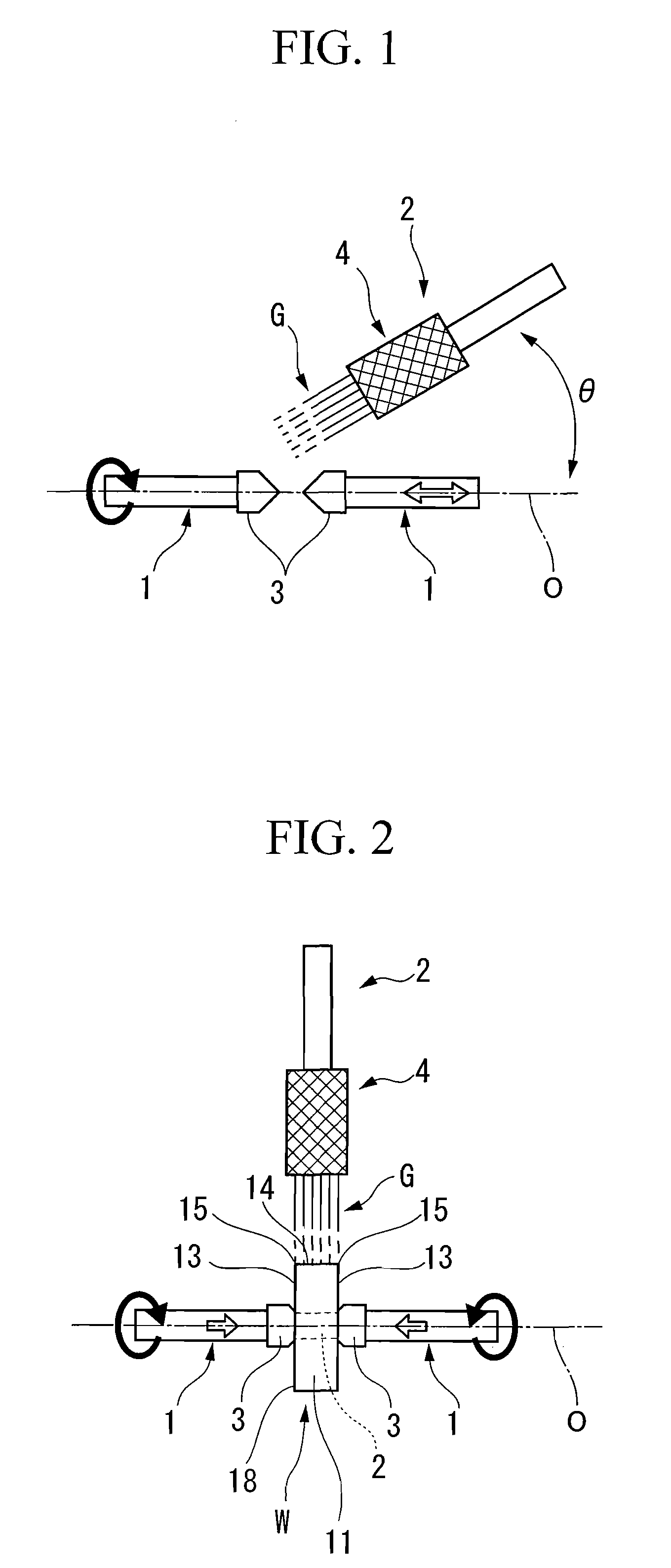
[0046]FIG. 1 shows an example of the equipment for manufacturing a surface-coated cutting insert relating to an embodiment (Embodiment 1) of the present invention, and FIG. 2 shows an embodiment of the present invention using this manufacturing equipment.

[0047]In the manufacturing equipment of FIG. 1, a pair of rotary shafts 1 are located with a spacing therebetween such that their front ends face each other, and are supported coaxially and rotatably in the same direction around an axis extending for example horizontally, and a blasting gun 2 for conducting the wet blasting by jetting an abrasive fluid G to the surface of a surface-coated cutting insert W held between these rotary shafts 1 as shown in FIG. 2 is provided on a side (upper side in FIG. 1) of this axis O.

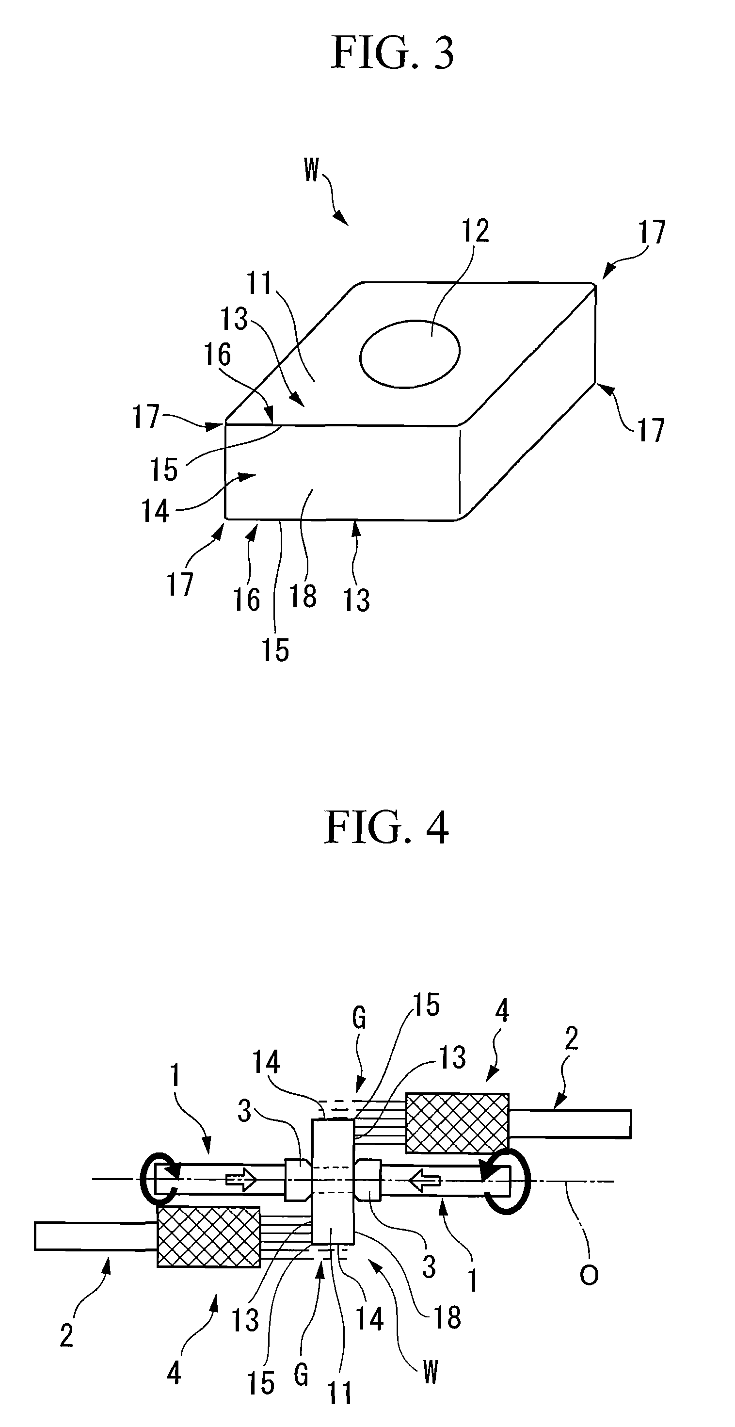
[0048]Here, an insert body 11 of the surface-coated cutting insert W which is subjected to the wet blasting treatment in this embodiment is formed in the shape of a polygonal plate (the shape of a rhombic plate in FIG. ...

embodiment 2

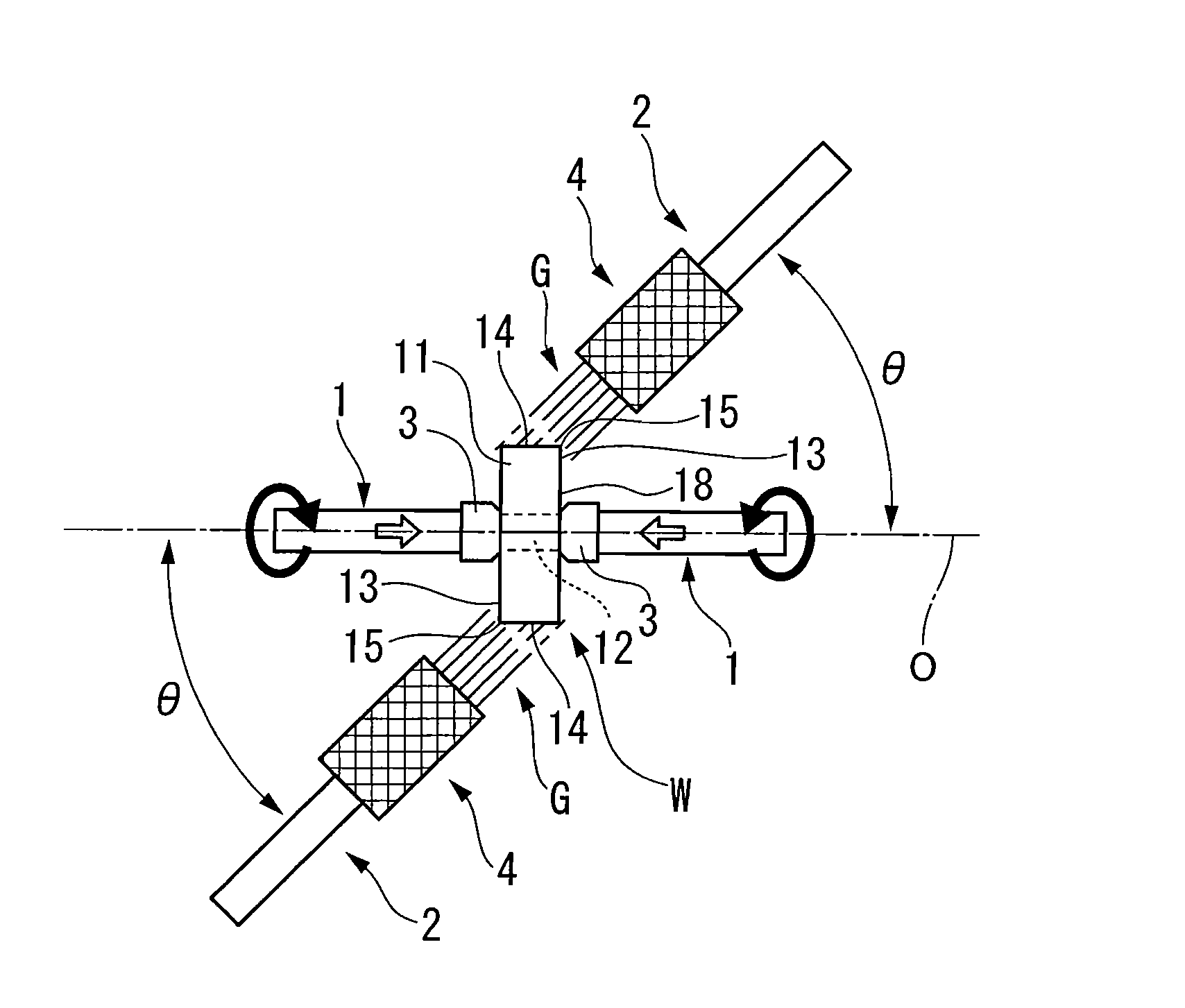
[0069]In this embodiment, the wet blasting treatment is mainly applied to the flank face 14 of the cutting insert W by one blasting gun 2 with the jetting angle of 90°. However, the wet blasting treatment of the rake faces 13 formed at the polygonal faces of the cutting insert and portions on the rake face 13 side at the intersecting edge line regions 15 may also be conducted by adjusting this jetting angle θ and setting it to 0°, i.e., setting it such that the axis O of the rotary shafts 1 and the jetting direction of the abrasive fluid G from the blasting gun 2 are parallel like Embodiment 2 shown in FIG. 4. In the manufacturing equipment relating to this embodiment, a plurality of (two in this embodiment) blasting guns 2 are located on the opposite sides by interposing the axis O of the rotary shafts 1, and are also located on the opposite sides in the direction of the axis O by interposing a portion between a pair of the rotary shafts 1 holding the cutting insert W. Namely, they...

embodiment 3

[0071]In the manufacturing method of the present invention based on such a manufacturing equipment, the blasting gun 2 may also be arranged by adjusting the jetting angle θ so that it makes an acute angle of more than 0° and less than 90° with the axis O, like Embodiment 3 shown in FIG. 5 (45° in FIG. 5), in addition to the embodiments shown in FIG. 2 and FIG. 4. In this case, the intersecting edge line region 15, the flank face 14 of cutting insert W which crosses at this intersecting edge line region 15 and the rake face 13 which is formed on one polygonal face of the insert body 11 can be simultaneously treated, for example, by conforming the central line of jetting of the abrasive fluid G from a blasting gun 2 to the vicinity of the intersecting edge line region 15. Accordingly, like the above embodiment, the entire surface of the cutting insert W can be subjected to wet blasting treated simultaneously and more efficiently with the rotation of rotary shafts 1 by arranging a plur...


PUM

PropertyMeasurementUnit
jetting angleaaaaaaaaaa
particle diameteraaaaaaaaaa

Abstract

This method for manufacturing a surface-coated cutting insert includes clamping and holding a surface-coated cutting insert with a pair of rotary shafts which are rotatable around an axis, and jetting an abrasive fluid to the surface of the surface-coated cutting insert using at least one blasting gun while rotating the surface-coated cutting insert, thereby, conducting wet blasting.

Description

BACKGROUND OF THE INVENTION[0001]1. Field of the Invention[0002]The present invention relates to a method for manufacturing a surface-coated cutting insert which is mounted to various insert-removable machine tools and is used for metal cutting.[0003]This application claims priority from Japanese Patent Application No. 2005-349651 filed on Dec. 2, 2005, the content of which is incorporated herein by reference.[0004]2. Background Art[0005]A cutting insert has an insert body with a hard material, such as tungsten carbide-based cemented carbide, titanium carbonitride-based cermet or ceramics, and the like as the substrate (e.g., in the shape of a polygonal plate), in which a cutting edge is formed at the intersecting edge line region of its rake face and flank face, and the cutting insert is mounted to insert-removable machine tools and has been widely used for metal cutting. As for such cutting inserts, surface-coated cutting inserts coated with a coating layer which is formed into a ...

Claims


Application Information

Patent Timeline
Patent Type & Authority Patents(United States)
IPC IPC(8): B24B1/00B23B27/14B24C1/04B24C3/00
CPCB24C1/02B24C1/10C23C30/005C23C14/588C23C16/56B24C3/22
Inventor OKADA, YOSHIKAZUSAEKI, TAKUSHIOHMORI, HIROSHI
Owner MITSUBISHI MATERIALS CORP
Why Eureka
Try Eureka