Laminate packaging flat cell

Active Publication Date: 2008-07-01
ENVISION AESC JAPAN LTD
View PDF14 Cites 8 Cited by
  • Summary
  • Abstract
  • Description
  • Claims
  • Application Information

AI Technical Summary

Benefits of technology

[0009]Moreover, the temperature of the electrode terminal lead sometimes reaches the softening point of the coating resin during the charge/discharge as described above. Furthermore, in some cases, peeling and crevices occur on a joint surface of the electrode terminal lead and the coating resin due to a difference between the thermal expansivity of the electrode terminal lead and the coating resin, and also due to the internal pressure of the cell, resulting in a lowering of the sealing capability. Due to the lowering of the sealing capability, which is described as above, there is a possibility that a liquid leakage will occur, in which an electrolytic solution or a decomposition product thereof oozes from an end of the electrode terminal lead in the cell and moves onto an interface between the electrode terminal

Problems solved by technology

However, in the above disclosed invention, though the sealing capability, when the cell is used for a camcorder, a cellular phone, a portable computer or the like or, in the initial term after the fabrication of the cell, is maintained, there is a possibility that the long-term reliability thereof under vibration conditions where the cell is mounted on the electric vehicle or the hybrid car cannot be maintained.
Meanwhile, though it is preferable to expand the area of the electrode terminal lead in order to control the resistance thereof, a joint surface between the laminate film and the electrode terminal lead is also expanded if the area of the electrode terminal lead is expanded, leading to yet more difficulty in ensuring the sealing capability.
Furthermore, in some cases, peeling and crevices occur on a joint surface of the electrode terminal lead and the coating resin due to a differ

Method used


Image

  • Laminate packaging flat cell
  • Laminate packaging flat cell
  • Laminate packaging flat cell

Examples


Example

EXAMPLE 1

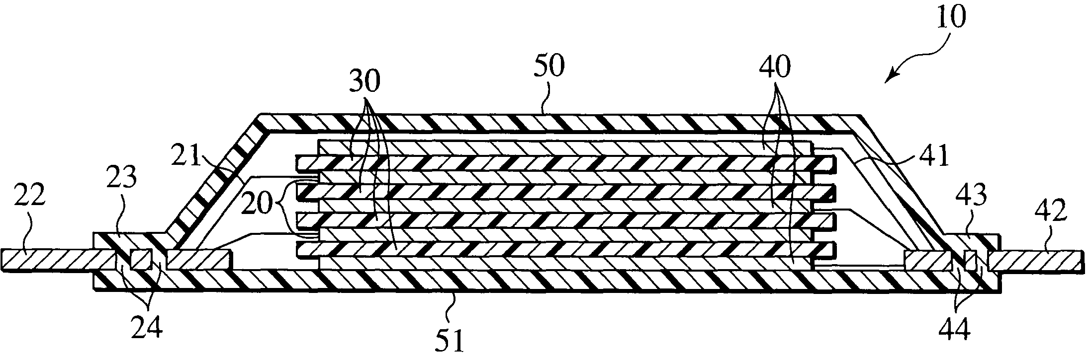
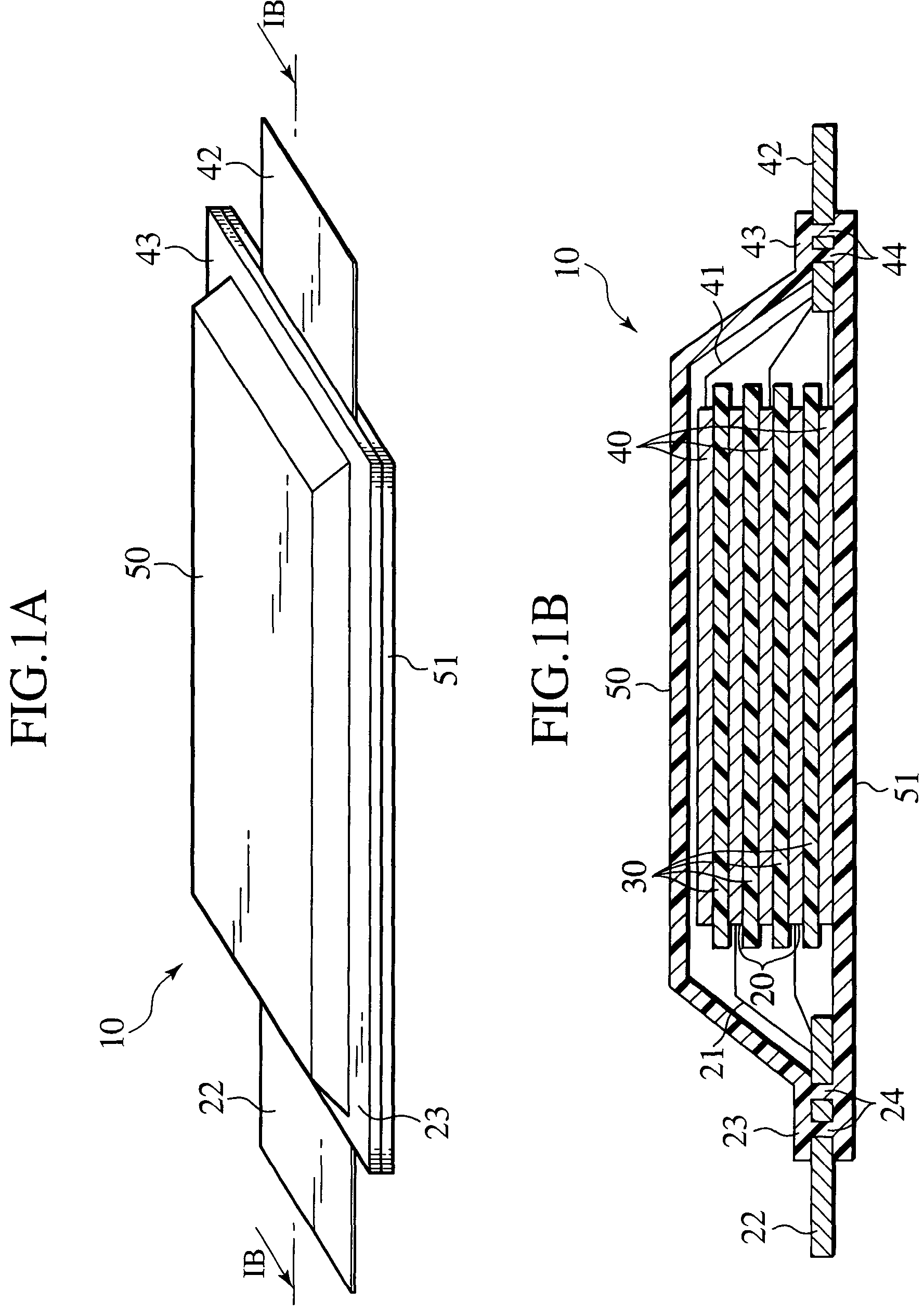
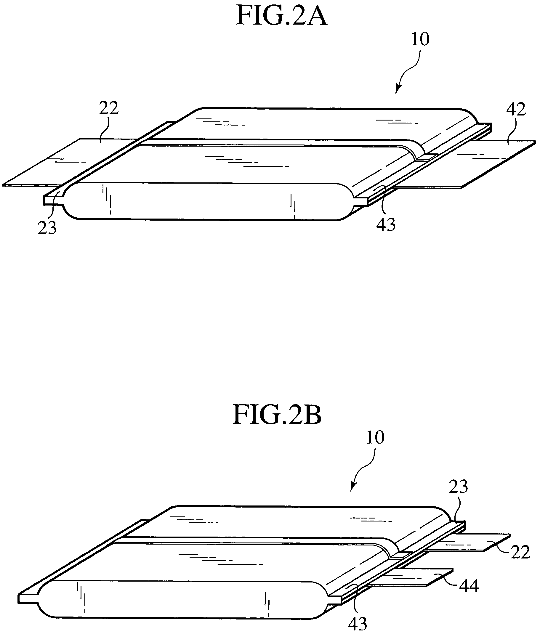
[0060]The laminate packaging flat cell shown in FIG. 1A was manufactured by use of laminate films, in each of which the thermal welding films were polypropylene and the metal film was aluminum.

[0061]For the electrodes, positive electrodes using LiMn2O4 as a positive electrode active material and negative electrodes using amorphous carbon as a negative electrode active material were used. For the positive terminal lead, an Al plate having a thickness of 150 μm was used. For the negative terminal lead, a Ni plate having a thickness of 150 μm was used. Each of the positive and negative terminal leads were 45 mm wide and 40 mm long. In each of the electrode terminal leads, three through-holes, each having a size of 5 mm×3 mm, were arrayed in one row at an interval of 7.5 mm. The ratio of the cross-sectional area of the through-holes to the cross-sectional area of each electrode terminal lead was 33%.

[0062]Adhesive layers formed of modified polypropylene, each having an area of ...

Example

EXAMPLE 2

[0064]Regarding the through-holes provided in each electrode terminal lead, four or five through-holes, each having a size of 4 mm×1 mm, were arrayed in each row at an interval of approximately 6 mm. Two of the described rows were provide in each electrode terminal lead. In a similar way to Example 1 except for the above, a laminate packaging flat cell was fabricated. The ratio of the cross-sectional area of the through-holes to the cross-sectional area of each terminal lead was 44%.

Example

EXAMPLE 3

[0065]An Al plate having a thickness of 300 μm was used for the positive terminal lead, and a Ni plate having a thickness of 300 μm was used for the negative terminal lead. In a similar way to Example 1 except for the above, a laminate packaging flat cell was fabricated.


PUM

PropertyMeasurementUnit
Fractionaaaaaaaaaa

Abstract

A laminate packaging flat cell comprises a laminate film formed by combining polymer and metal with each other; a power generating element formed of a plurality of electrode plates and separators, and hermetically sealed by the laminate film; and an electrode terminal lead coupled to the electrode plate. In the laminate packaging flat cell of the present invention, the power generating element is hermetically sealed by forming a thermally welded portion on an outer periphery of the laminate film, and the electrode terminal lead protrudes from the thermally welded portion, and a through-hole is provided in a position thereof contacting the thermally welded portion.

Description

BACKGROUND OF THE INVENTION[0001]1. Field of the Invention[0002]The present invention relates to a laminate packaging flat cell enhancing the stability of a thermally welded portion. More specifically, the present invention relates to a laminate packaging flat cell ensuring the stability of an electrode terminal lead and a laminate film in the thermally welded portion by providing a through-hole in the electrode terminal lead of the thermally welded portion, and further relates to a battery module and an assembled battery which are formed of the cells.[0003]2. Description of the Related Art[0004]Recently, air pollution caused by exhaust gas from vehicles has become a global problem. In such a context, electric vehicles, which use electric power as a motive power source, and hybrid cars, which are run by a combination of an engine and a motor, have been attracting attention. Correspondingly, the development of a cell having a high energy density and a high output density to be mounte...

Claims


Application Information

Patent Timeline
IPC IPC(8): H01M6/12H01M6/46H01M6/42H01M10/00H01M10/04H01M10/38H01M50/124H01M50/176H01M50/548H01M50/557H01M50/562
CPCH01M2/0212H01M2/0275H01M2/06H01M2/08H01M10/0413H01M10/0436H01M10/0445H01M2/0267Y10T29/4911H01M2/0287H01M2/30H01M10/0525H01M10/0585Y02T10/7011Y10T29/49114Y02E60/10Y02P70/50H01M50/557H01M50/124H01M50/562H01M50/176H01M50/548
Inventor SHIMAMURA, OSAMUABE, TAKAAKIITO, TAKANORISAITO, TAKAMITSUHORIE, HIDEAKISUGAWARA, HIROSHI
Owner ENVISION AESC JAPAN LTD
Why Eureka
Try Eureka