Adaptive control method for rapid thermal processing of a substrate

a technology of thermal processing and substrate, applied in the direction of semiconductor/solid-state device testing/measurement, optical radiation measurement, instruments, etc., can solve the problems of substrate temperature gradient, process may be detrimentally affected, non-uniform emissivity of substrate, etc., and achieve the effect of rapid thermal processing (rtp) of substra

Active Publication Date: 2008-07-15
APPLIED MATERIALS INC
View PDF3 Cites 16 Cited by
  • Summary
  • Abstract
  • Description
  • Claims
  • Application Information

AI Technical Summary

Benefits of technology

[0009]FIG. 2 is a flow chart illustrating a typical process sequence 200 for a rapid thermal process, such as the spike anneal process described above in conjunction with FIG. 1. Generally such a process begins with an initial temperature ramp 201 of the substrate. Until the substrate is at a temperature of about 300° C. to about 400° C., open-loop heating is performed during the first segment of initial temperature ramp 201. Referring back to FIG. 1, open-loop heating takes place between time 120 and 121. During open-loop heating, no substrate temperature feedback is incorporated into controlling the process and instead lamp power is applied to the substrate at pre-determined values for a pre-determined duration in order to heat the substrate to a temperature regime in which the substrate will be substantially opaque to the majority of lamp energy being applied to it. Below about 300° C. a typical RTP substrate, such as a silicon wafer, is largely transparent to much of the radiant energy produced by typical heating lamps. When this is the case, radiant energy that passes through the substrate may then be detected by the pyrometers that measure substrate backside temperature, producing an inaccurate substrate temperature measurement. For a closed-loop heating control algorithm, inaccurate substrate temperature measurement may result in serious control problems during the initial temperature ramp 201, such as instability and / or hunting. Open-loop heating is typically used at the beginning of RTP to avoid this problem. The set points for open-loop heating are generally determined empirically.

Problems solved by technology

For example, a substrate may have non-uniform emissivity because of spatial modifications to surface areas or volumes of the substrate.
In addition, substrate temperature gradients may be induced by localized gas cooling or heating effects related to processing chamber design as well as non-uniform endothermic or exothermic reactions that may occur on the substrate surface during processing.
If peak temperature 133 is exceeded during RTP, the process may be detrimentally affected in other ways, for example from unwanted diffusion of implanted atoms into the substrate or by exceeding the thermal budget of devices formed on the substrate.
For a closed-loop heating control algorithm, inaccurate substrate temperature measurement may result in serious control problems during the initial temperature ramp 201, such as instability and / or hunting.
The minimum time step size is generally limited by the sampling rate of the temperature sensors used to control the heating process.
A notable drawback of model-based controllers is that their ability to precisely control a substrate temperature to a desired time-temperature trajectory is limited by the accuracy of the assumptions on which the model is based.
However, because a controller's calculations are based on a specific substrate type with fixed optical properties, the model-based algorithm will be inherently inaccurate for all but a single type of substrate.
In practice, the edge region of a substrate is thermally affected by the periphery of the RTP chamber more than are other regions of the substrate, leading to chronic temperature non-uniformities residing in the edge region.
For very short processes, such as spike anneal processes, the control algorithm may not be able to compensate quickly enough, resulting in temperature non-uniformities near the edge of the substrate.
Further, because the current design of RTP chambers is geared toward radial temperature non-uniformity on a circular substrate, this method of temperature control is unable to correct non-radial temperature non-uniformities, for example a “cold spot” that is not symmetrically centered on the substrate.

Method used


Image

  • Adaptive control method for rapid thermal processing of a substrate
  • Adaptive control method for rapid thermal processing of a substrate
  • Adaptive control method for rapid thermal processing of a substrate

Examples


Embodiment Construction

[0038]The invention generally relates to methods and apparatus for the rapid thermal processing of a substrate. Embodiments contemplate the use of control algorithms for providing improved peak temperature repeatability, including a real-time adaptive control algorithm, a method for selecting a fixed control algorithm based on substrate properties and a combined method, wherein only a small number of zones utilize the adaptive control algorithm and the remainder are controlled by a computationally less intensive control algorithm.

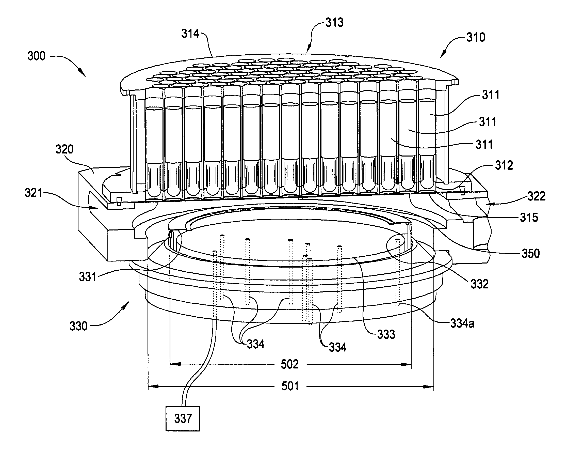
[0039]FIG. 3 is a partial perspective diagram of an exemplary RTP chamber that may incorporate embodiments of the invention. The exemplary RTP chamber, hereinafter referred to as chamber 300, has been cross-sectioned for clarity. The chamber 300 generally consists of a lamp assembly 310, a chamber body 320 and a substrate support assembly 330. For clarity, only the upper portion of chamber body 320 is illustrated in FIG. 3.

[0040]Lamp assembly 310 includes a...


PUM

PropertyMeasurementUnit
temperatureaaaaaaaaaa

Abstract

The present invention generally relates to methods for the rapid thermal processing (RTP) of a substrate. Embodiments of the invention include controlling a thermal process using either a real-time adaptive control algorithm or by using a control algorithm that is selected from a suite of fixed control algorithms designed for a variety of substrate types. Selection of the control algorithm is based on optical properties of the substrate measured during the thermal process. In one embodiment, a combination of control algorithms are used, wherein the majority of lamp groupings are controlled with a fixed control algorithm and a substantially smaller number of lamp zones are controlled by an adaptive control algorithm.

Description

BACKGROUND OF THE INVENTION[0001]1. Field of the Invention[0002]Embodiments of the present invention generally relate to methods of thermally processing a material such as a semiconductor substrate.[0003]2. Description of the Related Art[0004]A number of applications involve thermal processing of semiconductor and other materials, which require precise measurement and control of the temperature of the material. For instance, processing of a semiconductor substrate requires precise measurement and control of the temperature over a wide range of temperatures. One example of such processing is rapid thermal processing (RTP), which is used for a number of fabrication processes, including rapid thermal annealing (RTA), rapid thermal cleaning (RTC), rapid thermal chemical vapor deposition (RTCVD), rapid thermal oxidation (RTO), and rapid thermal nitridation (RTN). In the particular application of CMOS gate dielectric formation by RTO or RTN, thickness, growth temperature, and uniformity o...

Claims


Application Information

Patent Timeline
Patent Type & Authority Patents(United States)
IPC IPC(8): G01L9/06
CPCH01L22/12H01L2924/0002H01L2924/00G01K7/00G01R31/26H01L21/324H01L22/00
Inventor RANISH, JOSEPH MICHAELDIXIT, TARPANJENNINGS, DEANRAMACHANDRAN, BALASUBRAMANIANHUNTER, AARONADERHOLD, WOLFGANGADAMS, BRUCECHANG, WEN TEH
Owner APPLIED MATERIALS INC
Why Eureka
Try Eureka