Large area plasma source

a plasma source and large area technology, applied in plasma techniques, vacuum evaporation coating, ion beam tubes, etc., can solve the problems of limited thruster lifetime, and high backstreaming electron levels,

Inactive Publication Date: 2008-07-15
UNITED STATES GOVERNMENT ADMINISTRATOR OF NASA
View PDF22 Cites 45 Cited by
  • Summary
  • Abstract
  • Description
  • Claims
  • Application Information

AI Technical Summary

Problems solved by technology

In general, thruster lifetime is limited by essentially four potential failure modes: 1) discharge cathode failure, 2) neutralizer failure, 3) ion optics failure and 4) electron backstreaming.
Electron backstreaming becomes more and more of a problem as accelerator grid apertures widen due to erosion.
High levels of backstreaming electrons can destroy the discharge cathode.
Hollow cathode failure can occur after prolonged operation due to physical erosion or to the depletion of barium in the insert brought on by barium diffusion and subsequent evaporation or the formation of tungstates that tie up the barium.
Because of such phenomena, ion thruster hollow cathodes have a life of order 28,000 hours, which is not sufficient for those missions requiring more than three years of continuous thruster operation.
Also, the MUSES-C device suffers from cut-off issues associated with the way the microwaves are launched into its chamber (its microwave input port can be obstructed by the formation of a “throat” plasma in the port); the plasma source size is inherently small owing primarily to its higher frequency; power required to create a plasma ion is higher because ECR takes place closer to magnet rings, thereby increasing plasma losses to walls; and the device is inherently power limited because of the aforementioned throat plasma problem.
Electromagnets can be used to produce the magnetic fields needed for ECR plasma generation, but power demands of electromagnets preclude their use for low power space propulsion.
However, this device did not generate uniform plasmas (a consequence of its microwave injection scheme), and there was difficulty reaching predicted plasma densities.
Additionally, it operated at 5 GHz, an expensive frequency range; the method of microwave injection made it inherently difficult to generate uniform, larger area plasmas; and the device tended to “mode jump” (i.e., the plasma was not stable at all conditions).

Method used


Image

  • Large area plasma source
  • Large area plasma source
  • Large area plasma source

Examples


Embodiment Construction

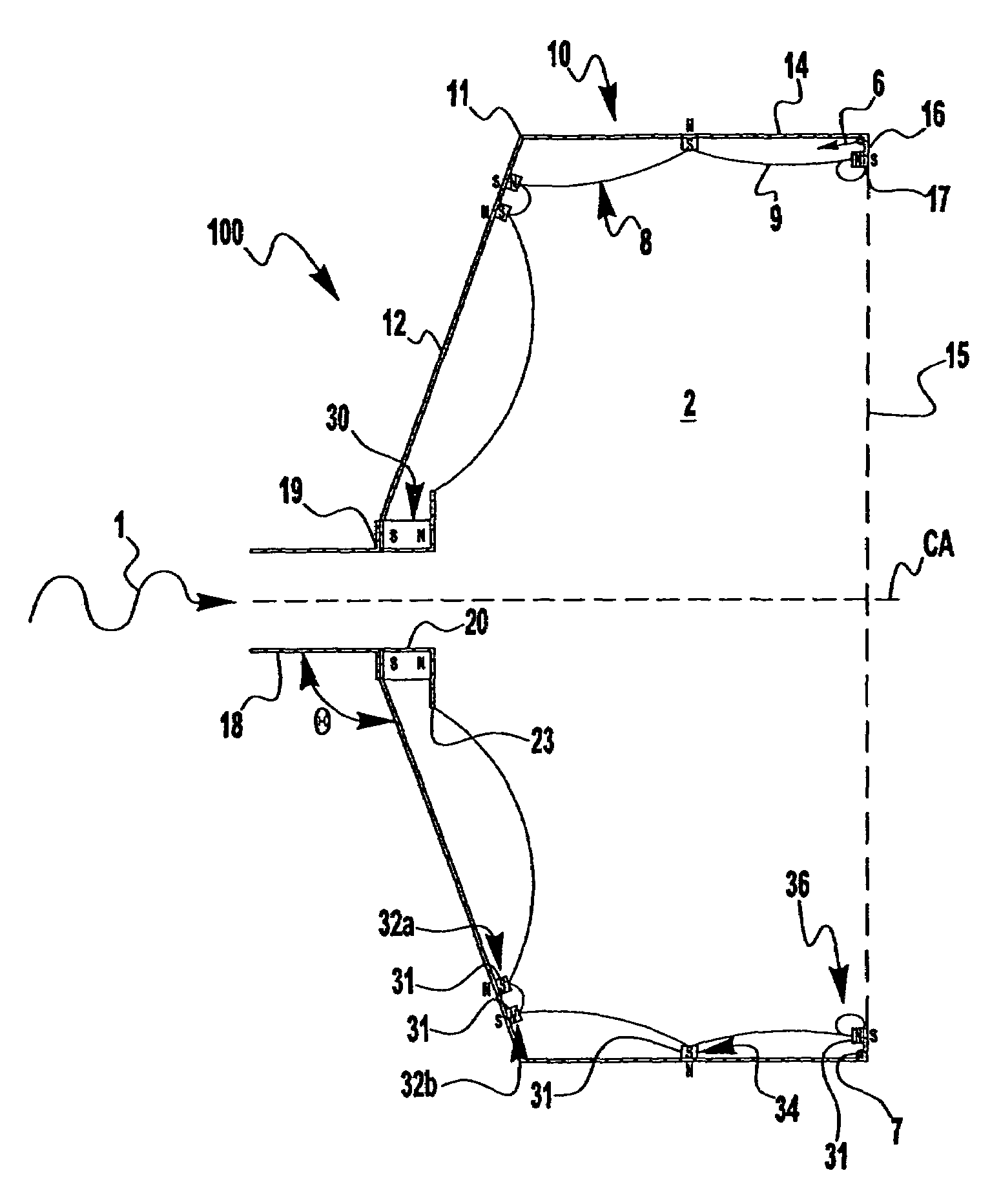
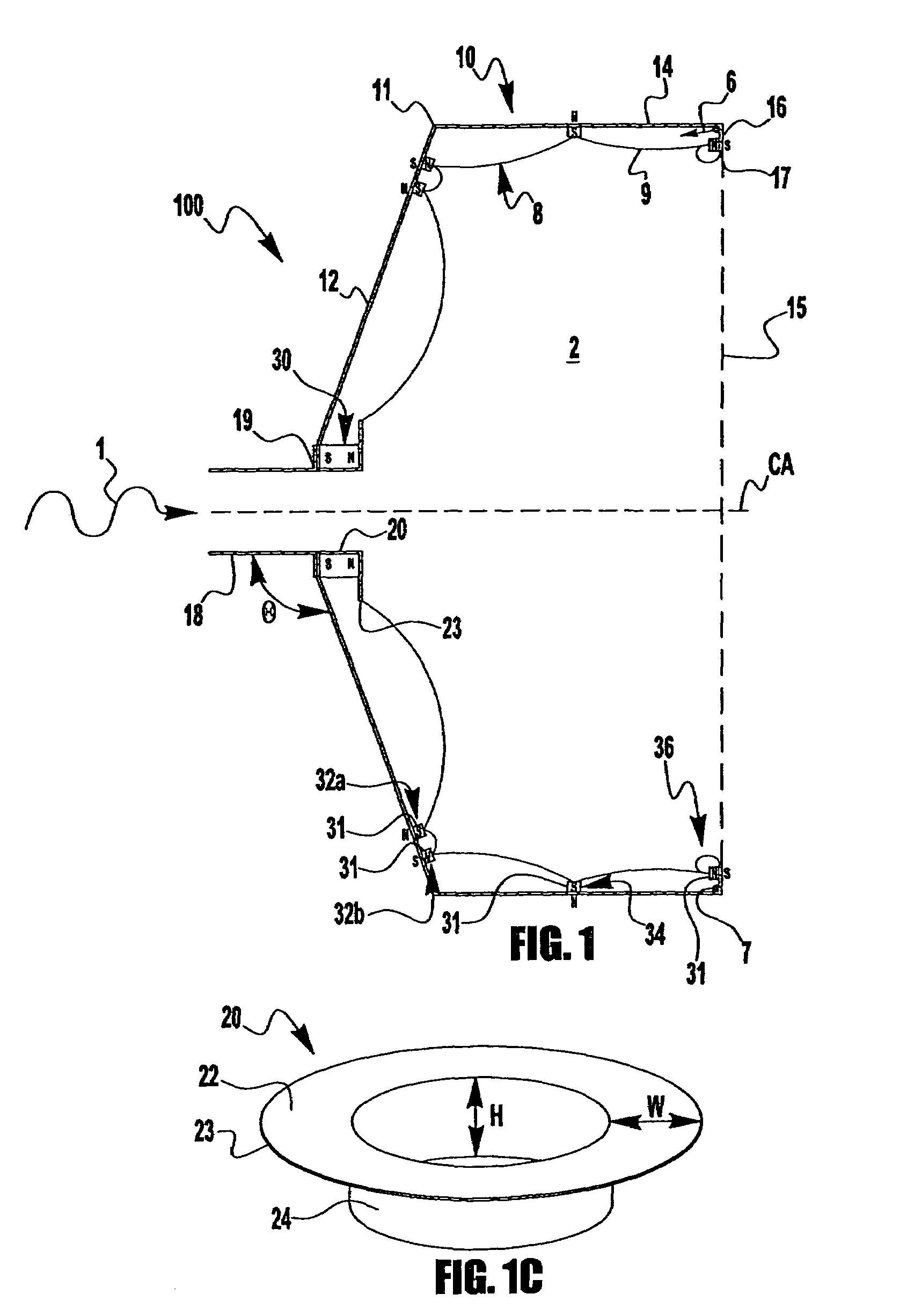
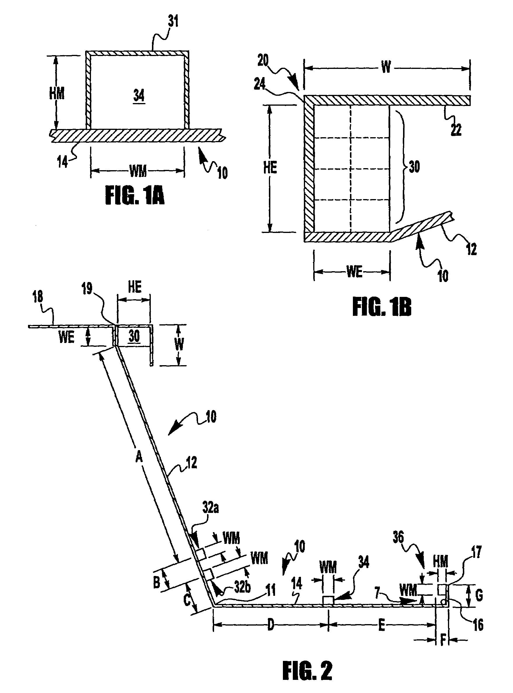
[0047]FIG. 1 shows a preferred embodiment of a large area, partial conic, plasma generator (source) 100 according to the present invention. A ring cusp magnetic circuit 8 (indicated by magnetic field lines 9) surrounding on-axis injection of microwaves 1 provides electron cyclotron resonance (ECR) ionization of a gas introduced via a reverse feed plenum (gas injection ring) 16. An important feature is the magnetic circuit 8 that is designed such that dense plasma formation at a microwave entrance hole 19 is prevented, thereby minimizing reflected power while enhancing microwave power coupling. A further important feature is optimization of the magnetic circuit 8 for enabling efficient microwave power coupling without a dielectric body or window (e.g., dielectric bodies used for impedance matching in the prior art). The arrangement of components forming the magnetic circuit 8 optimizes plasma production and heating with heating modes including ECR heating (e.g., right hand circularly...


PUM

PropertyMeasurementUnit
microwave frequencyaaaaaaaaaa
diameteraaaaaaaaaa
frequencyaaaaaaaaaa

Abstract

An all permanent magnet Electron Cyclotron Resonance, large diameter (e.g., 40 cm) plasma source suitable for ion / plasma processing or electric propulsion, is capable of producing uniform ion current densities at its exit plane at very low power (e.g., below 200 W), and is electrodeless to avoid sputtering or contamination issues. Microwave input power is efficiently coupled with an ionizing gas without using a dielectric microwave window and without developing a throat plasma by providing a ferromagnetic cylindrical chamber wall with a conical end narrowing to an axial entrance hole for microwaves supplied on-axis from an open-ended waveguide. Permanent magnet rings are attached inside the wall with alternating polarities against the wall. An entrance magnet ring surrounding the entrance hole has a ferromagnetic pole piece that extends into the chamber from the entrance hole to a continuing second face that extends radially across an inner pole of the entrance magnet ring.

Description

STATEMENT REGARDING FEDERALLY SPONSORED RESEARCH OR DEVELOPMENT[0001]The invention described herein was made by an employee of the United States Government and may be manufactured and used by or for the Government for Government purposes without the payment of any royalties thereon or therefore.TECHNICAL FIELD OF THE INVENTION[0002]The present invention relates to large area plasma sources, more particularly to electron cyclotron resonance (ECR) large area plasma sources, and most particularly to large area ECR plasma sources using only permanent magnets.BACKGROUND OF THE INVENTION[0003]The National Aeronautic and Space Administration (NASA) has determined a need to develop a long life plasma generator (source) for use as an ion propulsion device (e.g., an ion thruster) in long duration space missions. Requirements for the plasma source include: long life without maintenance, low power operation, high plasma density, and high plasma uniformity across its diameter.[0004]Propulsion sy...

Claims


Application Information

Patent Timeline
Patent Type & Authority Patents(United States)
IPC IPC(8): H01J7/24C23C14/00C23F1/00
CPCH01J27/18H05H1/54H01J37/32678H01J37/32357
Inventor FOSTER, JOHNPATTERSON, MICHAEL
Owner UNITED STATES GOVERNMENT ADMINISTRATOR OF NASA
Why Eureka
Try Eureka