Multi-channel communications transceiver

a transceiver and multi-channel technology, applied in the field of high-speed data communication, can solve the problems of inefficient bandwidth, more isi suffered by transmitted data, and difficulty in increasing data rates across backplane buses b>, and achieve the effect of increasing intersymbol interference and high data transmission rates

Inactive Publication Date: 2008-07-22
ENTROPIC COMM INC
View PDF87 Cites 81 Cited by
  • Summary
  • Abstract
  • Description
  • Claims
  • Application Information

AI Technical Summary

Benefits of technology

[0014]In accordance with the present invention, a data transmission system is presented that allows very high data transmission rates over a data bus that utilizes the signal attenuation properties of the copper based backplane interconnect system. In addition, this transmission scheme does not result in increased intersymbol interference at the receiver despite transmitting data at a very high speed. The data transmission system includes a transmitter system and a receiver system coupled through a transmission medium. The transmitter system receives parallel data having N bits and separates the N bits into (K+1) subsets for transmission into the base band and K frequency separated channels on the transmission medium. The receiver system receives the data from the base band and the K frequency separated channels from the transmission medium and recovers the N parallel bits of data. In some embodiments, the N parallel bits are separated into (K+1) subsets of bits, the (K+1) subsets of bits are encoded into (K+1) symbols, K of which are up-converted to a carrier frequency appropriate to that channel. The summed output signal resulting from the summation of the K up-converted channels and the baseband channel is transmitted over the transmission medium.

Problems solved by technology

One of the biggest problems with existing SERDES systems 100 is that they are very bandwidth inefficient, i.e., they require 3.125 GHz of bandwidth to transmit and receive 2.5 Gbps of data over a single pair of copper wires.
Therefore, it is very difficult to increase the data rates across backplane bus 110.
Therefore, the higher the data rate the more ISI suffered by the transmitted data.
In addition, electrical connectors and electrical connections (e.g., vias and other components) used in SERDES device 100 cause reflections, which also cause ISI.
However, in existing very high data-rate communication systems, equalization is very difficult to perform, if not impossible due to the high baud rate.
At higher data rates, conventional systems quickly become intractable due to the increased demands.
Transmitted data in each of the (K+1) channels can suffer from inter-symbol interference (ISI) as well as cross-channel interference due to harmonic generation in up-conversion and down-conversion processes in the transmitter and receiver.

Method used


Image

  • Multi-channel communications transceiver
  • Multi-channel communications transceiver
  • Multi-channel communications transceiver

Examples


Embodiment Construction

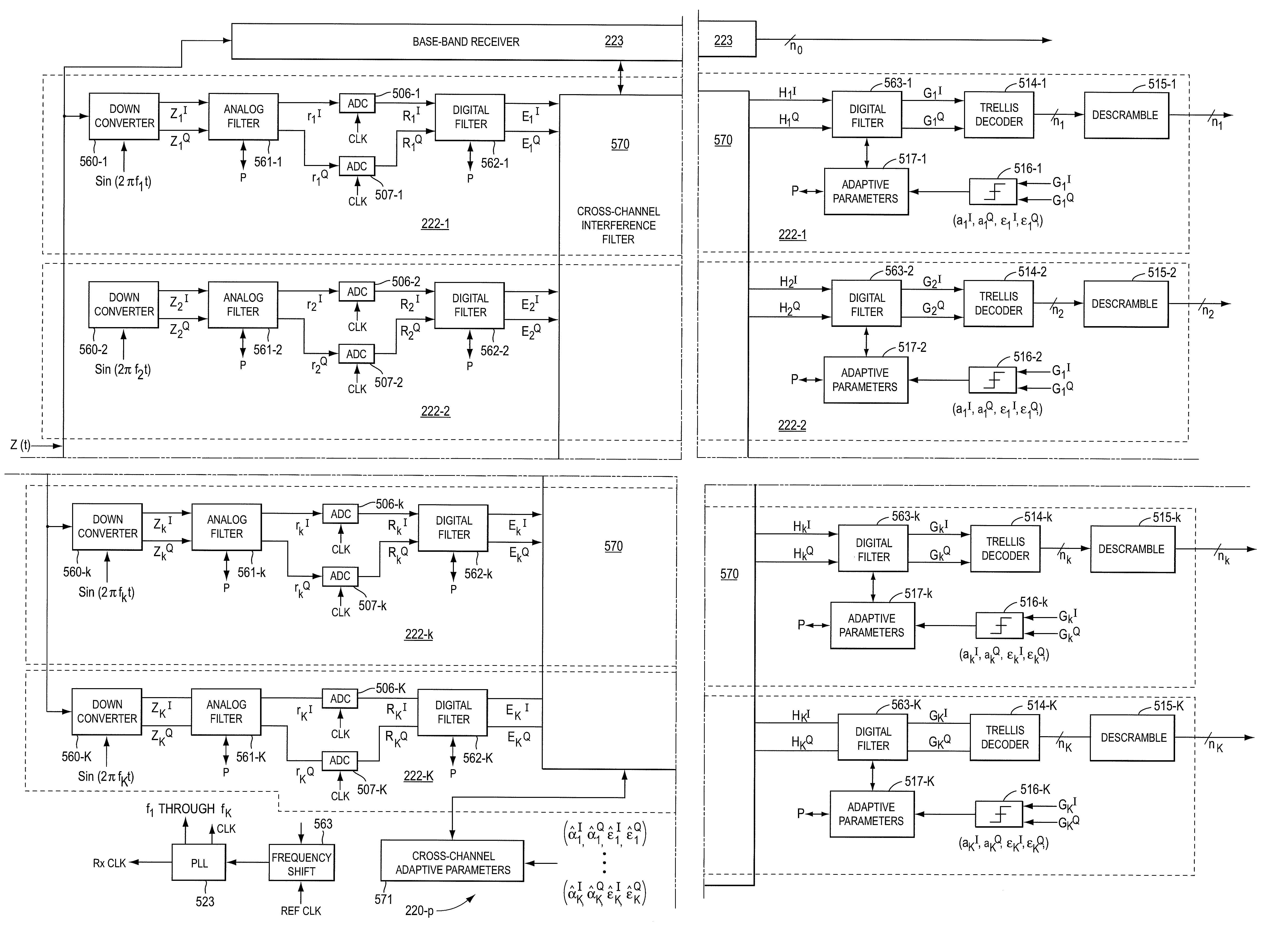
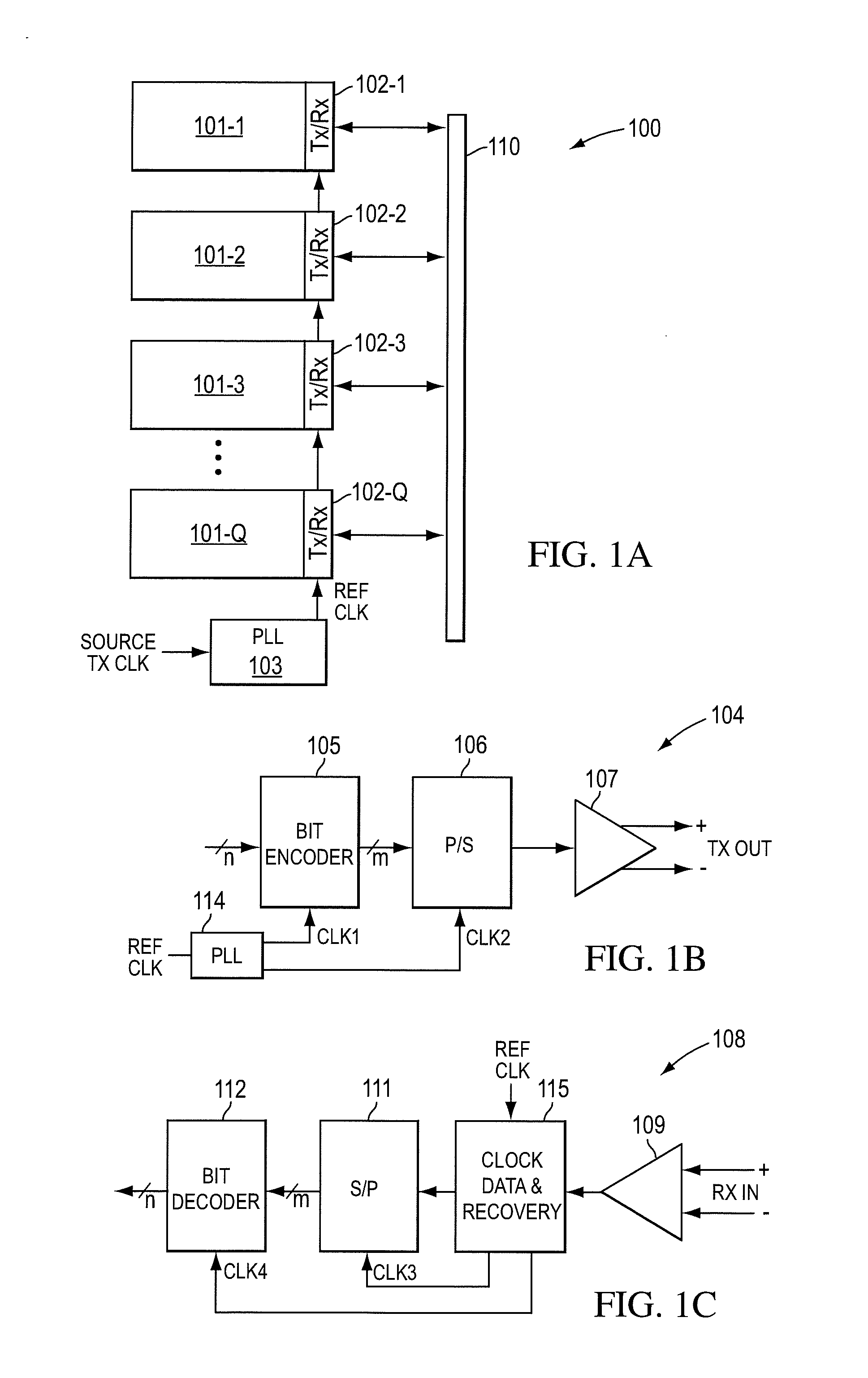
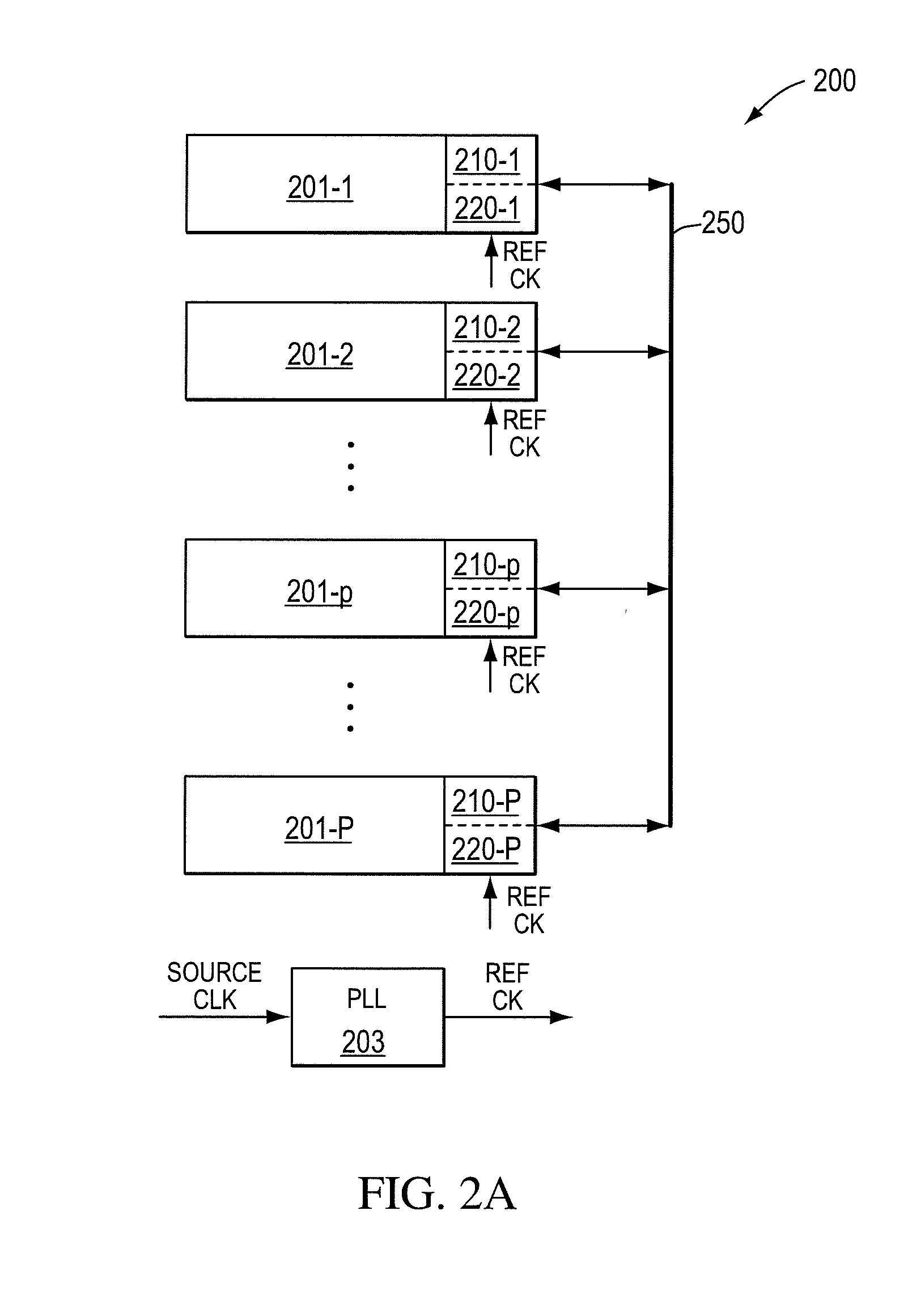
[0055]FIG. 2A shows a block diagram of a transmission system 200 according to the present invention. System 200 includes any number of components 201-1 through 201-P, with component 201-p representing an arbitrary one of components 201-1 through 201-P, coupled through a transmission medium 250. Transmission medium 250 may couple component 201-p to all of the components 201-1 through 201-P or may couple component 201-p to selected ones of components 201-1 through 201-P. In some embodiments, components 201-1 through 201-P are coupled through FR4 copper traces.

[0056]System 200 can represent any backplane system, any chassis-to-chassis digital communication system, or any chip-to-chip interconnect with components 201-1 through 201-P representing individual cards, cabinets, or chips, respectively.

[0057]Transmission channel 250 can represent any transmission channel, including optical channels, wireless channels, or metallic conductor channels such as copper wire or FR4 copper traces. Typ...


PUM


Abstract

A transceiver system according to the present invention transmits data utilizing the baseband and one or more frequency separated transmission bands. A baseband transmitter is combined with one or more transmitters that transmit data into one of the frequency separated transmission bands. A baseband receiver is combined with one or more receivers that receive data from the frequency separated transmission bands. Any combination of modulation systems can be utilized (e.g. PAM for the baseband and QAM for the frequency separated bands). A transceiver circuit or chip according to the present invention includes a transmitter and a receiver and communicates with a corresponding transceiver chip. In some embodiments, one baseband PAM transmitter is combined with one frequency separated QAM transmitter.

Description

RELATED APPLICATIONS[0001]The present disclosure is a continuation-in-part of U.S. application Ser. No. 10 / 167,158 filed on Jun. 10, 2002 to Sreen A. Raghavan, Tulasinath G. Manickam, Peter J. Sallaway, and Gerard E. Taylor, which is a continuation-in-part of U.S. application Ser. No. 10 / 071,771 filed on Feb. 6, 2002 to Sreen A. Raghavan, Thulasinath G. Manickam, Peter J. Sallaway, and Gerard E. Taylor, which is a continuation-in-part of U.S. application Ser. No. 09 / 965,242 to Sreen Raghavan, Thulasinath G. Manickam, and Peter J. Sallaway, filed Sep. 26, 2001, which is a continuation-in-part of U.S. application Ser. No. 09 / 904,432, by Sreen Raghavan, filed on Jul. 11, 2001, assigned to the same entity as is the present application, each of which are herein incorporated by reference in its entirety.BACKGROUND[0002]1. Field of the Invention[0003]The present invention is related to high-speed communications of data in a communication system and, in particular, to high data rate transmi...

Claims


Application Information

Patent Timeline
Patent Type & Authority Patents(United States)
IPC IPC(8): H04B17/02H04B17/40H04L27/26
CPCH04L27/2601
Inventor RAGHAVAN, SREEN A.MANICKAM, THULASINATH G.SALLAWAY, PETER J.TAYLOR, GERARD E.
Owner ENTROPIC COMM INC
Why Eureka
Try Eureka