Clock generator circuit using phase modulation technology and method thereof

a phase modulation and clock generator technology, applied in the direction of amplitude demodulation, line-fault/interference reduction, pulse technique, etc., can solve the problems increasing the volume of the circuit device, and increasing the speed of other devices in the system, so as to achieve the effect of reducing the size of the circuit devi

Active Publication Date: 2008-07-29
REALTEK SEMICON CORP
View PDF6 Cites 18 Cited by
  • Summary
  • Abstract
  • Description
  • Claims
  • Application Information

AI Technical Summary

Benefits of technology

[0012]It is therefore one of the objects of the invention to provide a phase lock loop circuit using phase modulation technology, wherein a modulation signal does not have to b

Problems solved by technology

1. Because the loop bandwidth of the PLL is smaller than the frequency of the modulation signal, the area of the capacitor in the loop filter 13 has to be enlarged, and thus the volume of the circuit device is also enlarged.
2. The conventional method can only perform the center spread spectrum but cannot perform the down spread spectrum. In general, the condition of the up spread spectrum may have the problem that the speeds of other devices in the system are not sufficiently high, but the condition of the down spread spectrum is usually free f

Method used


Image

  • Clock generator circuit using phase modulation technology and method thereof
  • Clock generator circuit using phase modulation technology and method thereof
  • Clock generator circuit using phase modulation technology and method thereof

Examples


Embodiment Construction

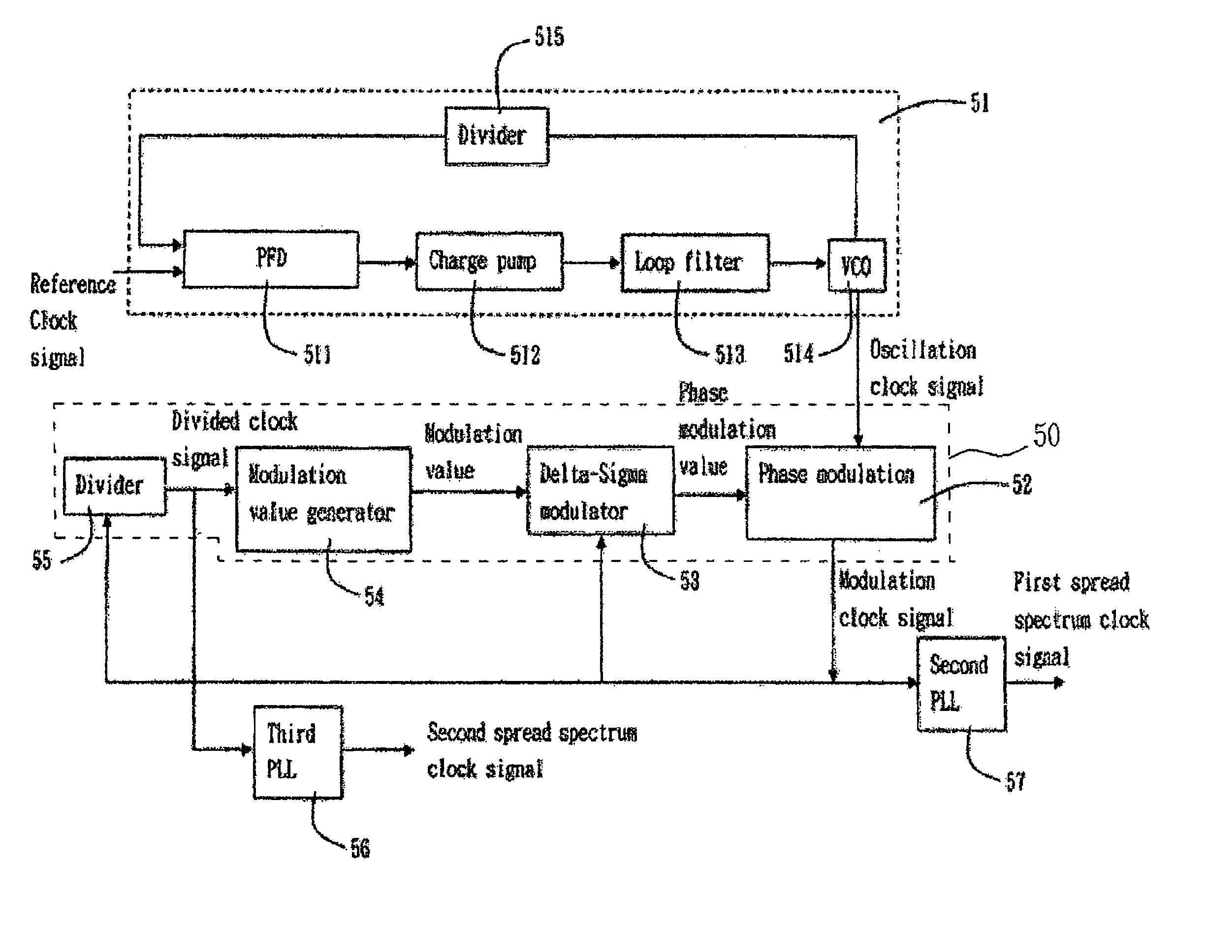
[0032]FIG. 5A is a block diagram showing a spread spectrum circuit using phase modulation technology according to an embodiment of the invention. The circuit includes a multi-phase oscillation clock generator 51, and a spread spectrum control circuit 50 comprising a modulation value generator 54, a Delta-Sigma modulator 53, a phase modulator 52, a divider 55, and a second phase-locked loop (PLL) 57. The multi-phase oscillation clock generator 51 may be a phase-locked loop (PLL), which is composed of a phase frequency detector (PFD) 511, a charge pump 512, a loop filter 513, a voltage controlled oscillator (VCO) 514, and a divider 515.

[0033]The multi-phase oscillation clock generator 51 receives a reference clock signal and outputs a plurality of oscillation clock signals having the same frequency but different phases, and the waveforms of the signals are shown in FIG. 6. In the waveforms of FIG. 6, it is assumed that the oscillation clock signals have eight phases (P0 to P7) in one ...


PUM


Abstract

A clock generator circuit, comprising: a multi-phase clock signal generator for generating a plurality of clock signals having a same frequency but difference phases according to a reference clock signal; a modulation device for generating a phase modulation signal through Delta-Sigma modulation; and a phase modulator, which is electrically coupled to the modulation device, for selecting one of the clock signals to be a modulated clock signal according to the phase modulation signal.

Description

[0001]This application claims the benefit of Taiwan application Ser. No. 092115156, filed Jun. 3, 2003, the subject matter of which is incorporated herein by reference.BACKGROUND OF THE INVENTION[0002]1. Field of the Invention[0003]The invention relates to a clock generator circuit and a method thereof, and more particularly to a clock generator circuit using phase modulation technology and a method thereof.[0004]2. Description of the Related Art[0005]Spread spectrum can reduce energy having a converged frequency and thus decrease the electromagnetic interference on other electrical devices. FIG. 1 is a schematic block diagram showing a spread spectrum circuit using a phase-locked loop (PLL). The PLL includes a phase frequency detector (PFD) 11, a charge pump 12, a loop filter 13, a voltage controlled oscillator (VCO) 14, and a divider 15. The spread spectrum circuit in the conventional PLL is configured such that a modulation signal is applied to a connection between the charge pum...

Claims


Application Information

Patent Timeline
IPC IPC(8): H03D3/24H03C3/09H03K7/04H03L7/07H03L7/099H04B15/04
CPCH03C3/0966H03K7/04H03L7/07H03L7/0998H04B15/04H03L7/0996H04B2215/067H04B2215/064
Inventor WANG, PING-YING
Owner REALTEK SEMICON CORP
Why Eureka
Try Eureka