Method for measuring reaction rate coefficient by surface plasmon resonance analysis

a surface plasmon and reaction rate coefficient technology, applied in the field of surface plasmon resonance analysis, can solve the problems of significant differential signal error generation, significant signal level variation, and generation of new fitting error, and achieve excellent accuracy, reliability and cost performance, and improve assay accuracy. the effect of accuracy and simplifying the apparatus

Inactive Publication Date: 2008-08-19
FUJIFILM CORP +1
View PDF9 Cites 3 Cited by
  • Summary
  • Abstract
  • Description
  • Claims
  • Application Information

AI Technical Summary

Benefits of technology

[0009]An object of the present invention is to provide a method for measuring a rate coefficient by surface plasmon resonance analysis with excellent accuracy, reliability, and cost performance that can improve the assay accuracy and simplify the apparatus.

Problems solved by technology

However, since conventional methods require complicated operations or labeling substances, several techniques are used that are capable of detecting the change in the binding amount of a test substance with high sensitivity without using such labeling substances.
It should be noted that, in actual assay, a liquid flow becomes unstable via liquid exchange at the time of analyte addition or washing, which generates significant variations in signal levels.
When detection and reception of control signals are obtained on several surfaces, a significant differential signal error is generated due to a time lag between those surfaces (and differences in concentrations caused thereupon) or other reasons.
Provision of a “dead time,” however, results in generation of a new fitting error.
Such an error inevitably enlarges as the “dead time” increases (see FIG. 4).
With the use of an actual apparatus, however, such requirement was difficult to comply with.
Even if it was achieved, preparation thereof was very complicated and cost-consuming.

Method used


Image

  • Method for measuring reaction rate coefficient by surface plasmon resonance analysis
  • Method for measuring reaction rate coefficient by surface plasmon resonance analysis
  • Method for measuring reaction rate coefficient by surface plasmon resonance analysis

Examples


examples

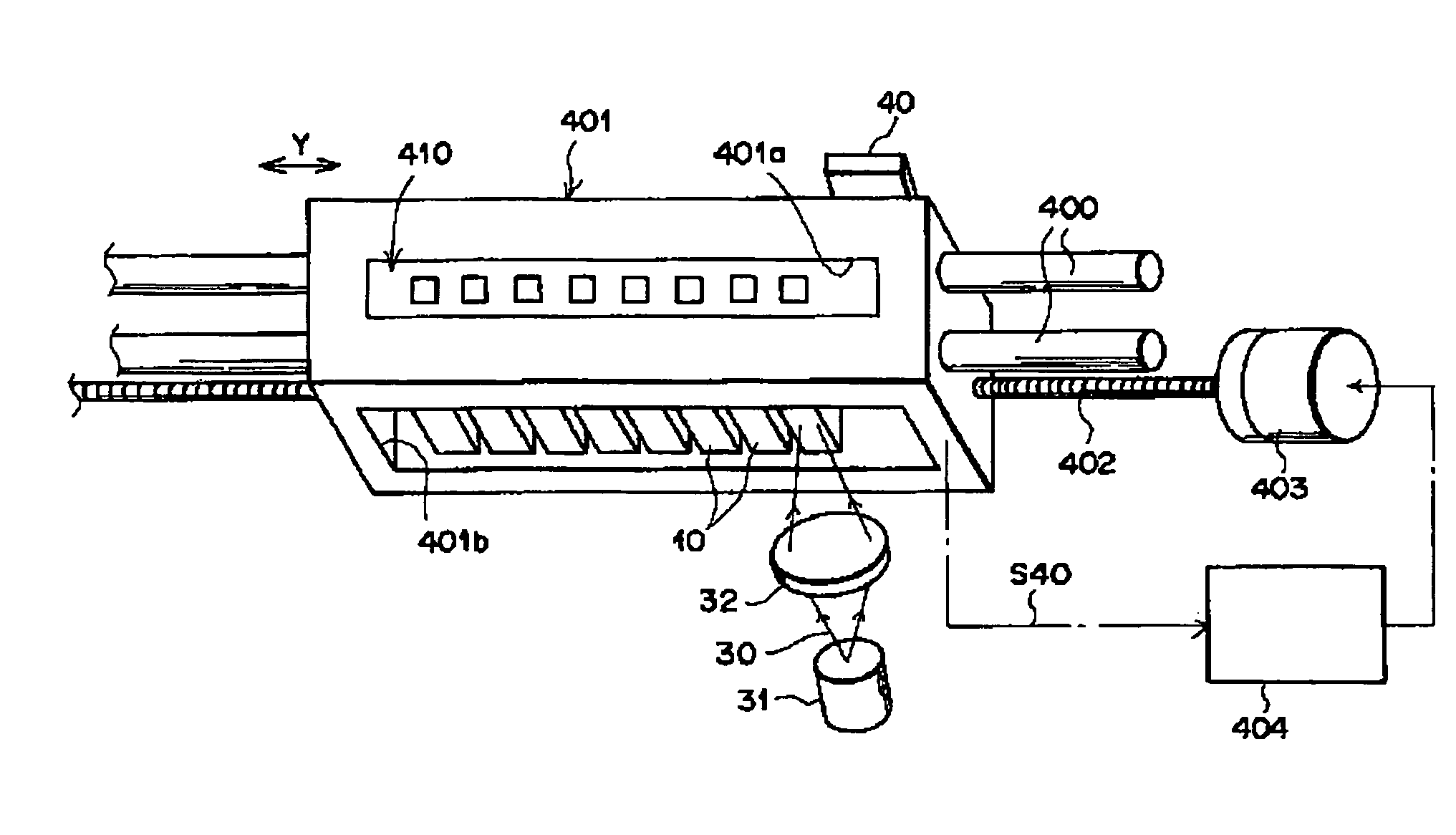
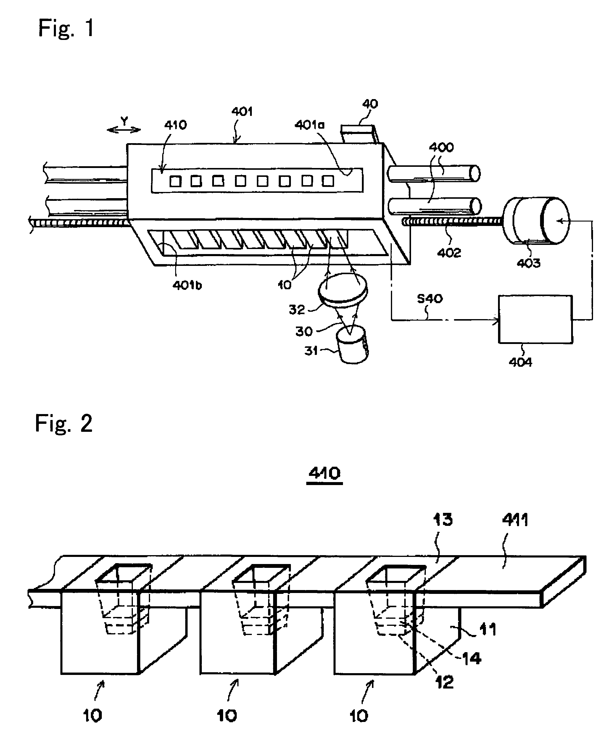
[0107]The following experiment was carried out using a device shown in FIG. 22 of Japanese Patent Laid-Open No. 2001-330560 (hereinafter referred to as the surface plasmon resonance measurement device of the present invention) (shown in FIG. 1 of the present specification) and a dielectric block shown in FIG. 23 of Japanese Patent Laid-Open No. 2001-330560 (hereinafter referred to as the dielectric block of the present invention) (shown in FIG. 2 of the present specification).

[0108]In the surface plasmon resonance measurement device shown in FIG. 1, a slide block 401 is used as a supporting medium for supporting measurement units, which is joined to two guide rods 400, 400 placed in parallel with each other while flexibly sliding in contact, and which also flexibly moves linearly along the two rods in the direction of an arrow Y in the figure. The slide block 401 is screwed together with a precision screw 402 placed in parallel with the above guide rods 400, 400, and the precision s...


PUM

PropertyMeasurementUnit
timeaaaaaaaaaa
timeaaaaaaaaaa
timeaaaaaaaaaa

Abstract

An object of the present invention is to provide a method for measuring a rate coefficient by surface plasmon resonance analysis with excellent accuracy, reliability, and cost performance that can improve the assay accuracy and simplify the apparatus. The present invention is provides a method for determining the adsorption rate coefficient (Ka) and the dissociation rate coefficient (Kd) of the reaction between an analyte molecule immobilized on a metal surface and a molecule that interacts with the analyte molecule by measuring changes in surface plasmon resonance signals using a surface plasmon resonance measurement device and performing fitting to a signal curve obtained by such measurement, wherein fitting is performed to the signals from which data obtained at the time of liquid exchange and data obtained at a given time point thereafter have been removed, and that an algorithm is adopted wherein the fitted curve passes through a point representing a baseline value obtained at the time of liquid exchange or immediately therebefore.

Description

TECHNICAL FIELD[0001]The present invention relates to a method for measuring the rate coefficient of the reaction between an analyte molecule immobilized on a metal surface and a molecule that interacts with the analyte molecule by surface plasmon resonance analysis.BACKGROUND ART[0002]Recently, a large number of measurements using intermolecular interactions such as immune responses are being carried out in clinical tests, etc. However, since conventional methods require complicated operations or labeling substances, several techniques are used that are capable of detecting the change in the binding amount of a test substance with high sensitivity without using such labeling substances. Examples of such a technique may include a surface plasmon resonance (SPR) measurement technique, a quartz crystal microbalance (QCM) measurement technique, and a measurement technique of using functional surfaces ranging from gold colloid particles to ultra-fine particles. The SPR measurement techn...

Claims


Application Information

Patent Timeline
Patent Type & Authority Patents(United States)
IPC IPC(8): G01N33/553G01N21/27G01N21/41
CPCG01N21/553Y10S436/805
Inventor OHTSUKA, HISASHI
Owner FUJIFILM CORP
Why Eureka
Try Eureka