Electronic device and pressure sensor

Active Publication Date: 2008-08-19
HITACHI ASTEMO LTD
View PDF14 Cites 1 Cited by
  • Summary
  • Abstract
  • Description
  • Claims
  • Application Information

AI Technical Summary

Benefits of technology

[0009]Accordingly, it is an object of the present invention to ensure a necessary thickness of a joining substance while preventing a position shift of a mounted electronic component, thereby increasing reliability in protectio

Problems solved by technology

This has invited a problem of variations in thickness of the joining substance.
By experiments, it has been confirmed that, when an electronic component is mounted between leads integrally molded with a resin-made package case, cracks generate and spread in the joining substance due to thermal stresses caused based on the difference between the coefficients of linear expansions of component materials used.
Further, when an electronic component is bonded using a solder

Method used


Image

  • Electronic device and pressure sensor
  • Electronic device and pressure sensor
  • Electronic device and pressure sensor

Examples


Embodiment Construction

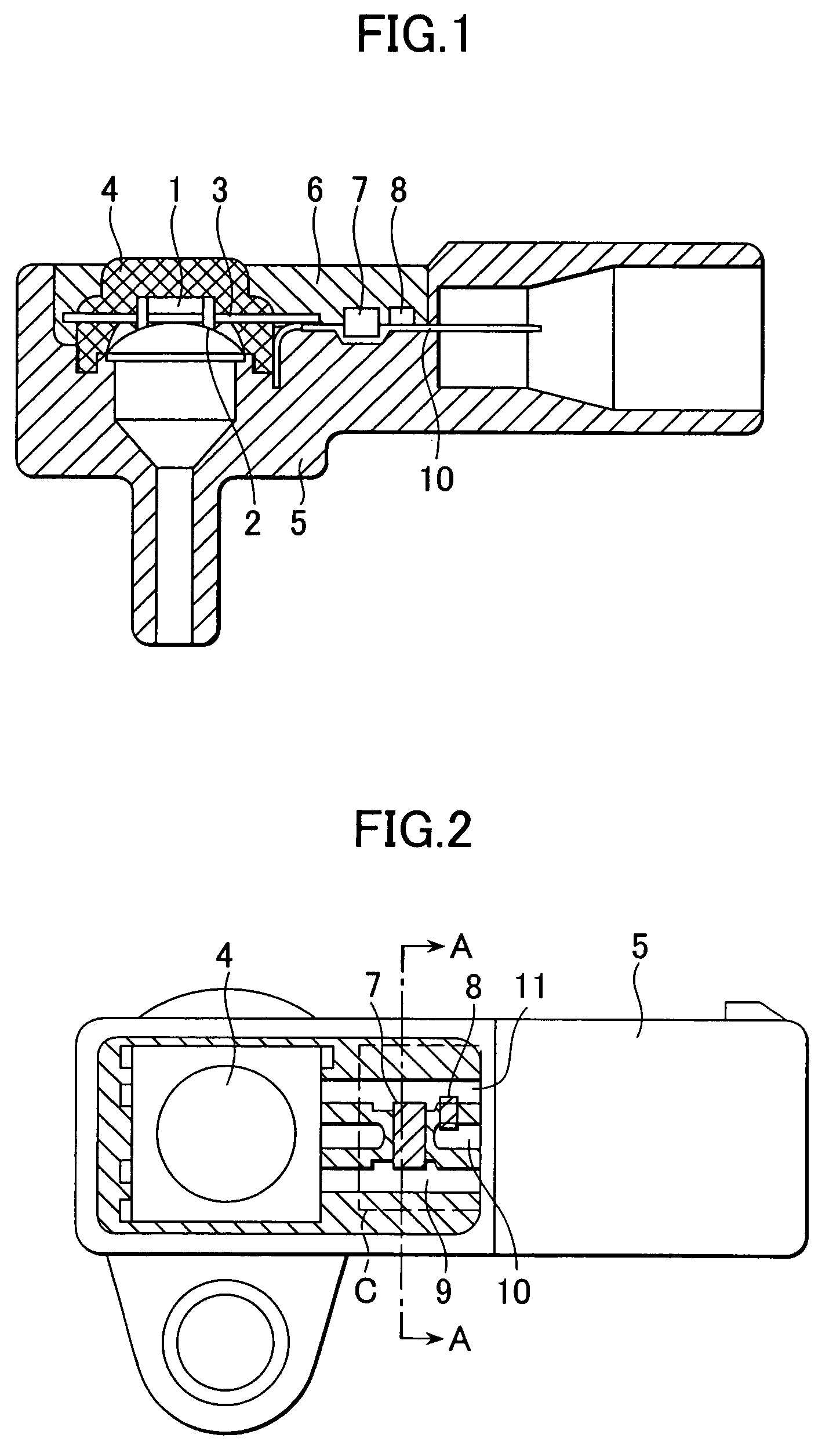
[0026]The construction of one embodiment of the present invention will be described below with reference to FIGS. 1 and 2.

[0027]FIG. 1 is a longitudinal sectional view of a pressure sensor according to one embodiment of the present invention, and FIG. 2 is a front view of the pressure sensor.

[0028]A sensing unit 1 is constructed by forming a diaphragm and a circuit on a silicon wafer and connecting the silicon wafer to a glass base by anodic bonding.

[0029]A sensing unit case 4 is made of thermosetting resin such as an epoxy resin or thermoplastic resin such as PPS (polyphenylene sulfide). Sensing unit terminals 3 are each made of phosphor copper plated with nickel.

[0030]The sensing unit 1 is fixedly bonded to the sensing unit case 4. The sensing unit terminals 3 and the sensing unit 1 both insert-molded in the sensing unit case 4 are connected to each other by connecting wires 2 of aluminum or gold for electrical connecting between them.

[0031]A package case 5 comprises a resin mater...


PUM


Abstract

An electronic device requires an electronic component to be mounted for the purpose of static shielding. The mounting of such an electronic component raises a problem of avoiding thermal stresses and cracks generated due to the difference between the coefficients of linear expansion of component materials. A positioning recess, a joining-substance thickness ensuring recess, a joining-substance thickness ensuring projection, etc. are formed in a combined manner in an electronic component mount portion of each of leads, whereby spreading of cracks generated in the joining substance can be suppressed and reliability can be improved. Filling a sealing material so as to seal and restrain the electronic component mounted in the electronic component mount portion without leaving voids contributes to further suppressing spreading of cracks generated in the joining substance and ensuring more improved reliability of the joining substance.

Description

BACKGROUND OF THE INVENTION[0001]1. Field of the Invention[0002]The present invention relates to general electronic devices including an airflow sensor, a rotation signal sensor, an angle sensor, and an igniter, as well as a pressure sensor. More particularly, the present invention relates to a structure for mounting, in a package case integrally molded with leads, an electronic circuit for issuing an output signal and an electronic component for reducing an electric disturbance.[0003]2. Description of the Related Art[0004]As disclosed in JP-A-11-145180, there is known a method of preventing a position shift of an electronic component by forming a recess for positioning of the electronic component to be mounted.[0005]On the other hand, for example, a capacitor with a lead wire is also known which is used as an electronic component for reducing an electric disturbance. However, such a capacitor has problems that its relatively bulky shape impedes a size reduction and the component is...

Claims


Application Information

Patent Timeline
IPC IPC(8): H01L23/48H01L29/84G01L9/00H05K3/20H05K3/28H05K3/34
CPCH05K3/3442H05K3/202H05K3/284H05K2201/09036H05K2201/09745H01L2924/0002H05K2201/10636H01L2924/00Y02P70/50
Inventor EBINE, HIROMICHIKIKUCHI, KATSUHIKOSHIMADA, SATOSHIHAYASHI, MASAHIDE
Owner HITACHI ASTEMO LTD
Why Eureka
Try Eureka