Damping control in a three-phase motor with a single current sensor

a three-phase motor and current sensor technology, applied in the direction of dynamo-electric converter control, program control, instruments, etc., can solve the problems of inability to measure the internal circulation of current within the motor winding in damping mode by a single external resistor, and the system requires three current sensors

Inactive Publication Date: 2008-08-19
CONTINENTAL AUTOMOTIVE SYST INC
View PDF33 Cites 34 Cited by
  • Summary
  • Abstract
  • Description
  • Claims
  • Application Information

AI Technical Summary

Benefits of technology

[0022]It is possible for the powered mechanical systems to exhibit a lightly-damped resonant response within a specific frequency region (e.g. 5-10 Hz) due to the mechanical properties of the system and the closed loop response of the controller. However, it is desirable that the closed-loop control system remain stable for all possible mechanical disturbances. If a mechanical disturbance is encountered which is in the frequency range where a lightly damped system response occurs, the controller operation must be modified such that system stability is maintained. The system response is defined as the closed loop response of the mechanical system and the electronic controller. One way to ensure system stability is to short the motor windings. This action has the consequence of damping the motor and mechanical system response because the motor acts as a brake to oppose any motion induced by the mechanical system.

Problems solved by technology

This type of system has the disadvantage of requiring three current sensors, one for each of the three phase windings, and three measurement circuits.
Not only are unstable mechanical resonances undesired by themselves, these resonances can generating an electromotive force (EMF) that can result in excess current in the motor.
However, the internal circulation of currents within the motor windings in damping mode cannot be measured by a single external resistor since the resistor is not in a current carrying loop.
Therefore, the currents within the motor windings cannot be measured, and therefore cannot be modified or controlled.
Consequently, the voltage developed across this resistor is negative and cannot be read by the controller unless the controller is designed for this case.

Method used


Image

  • Damping control in a three-phase motor with a single current sensor
  • Damping control in a three-phase motor with a single current sensor
  • Damping control in a three-phase motor with a single current sensor

Examples


Embodiment Construction

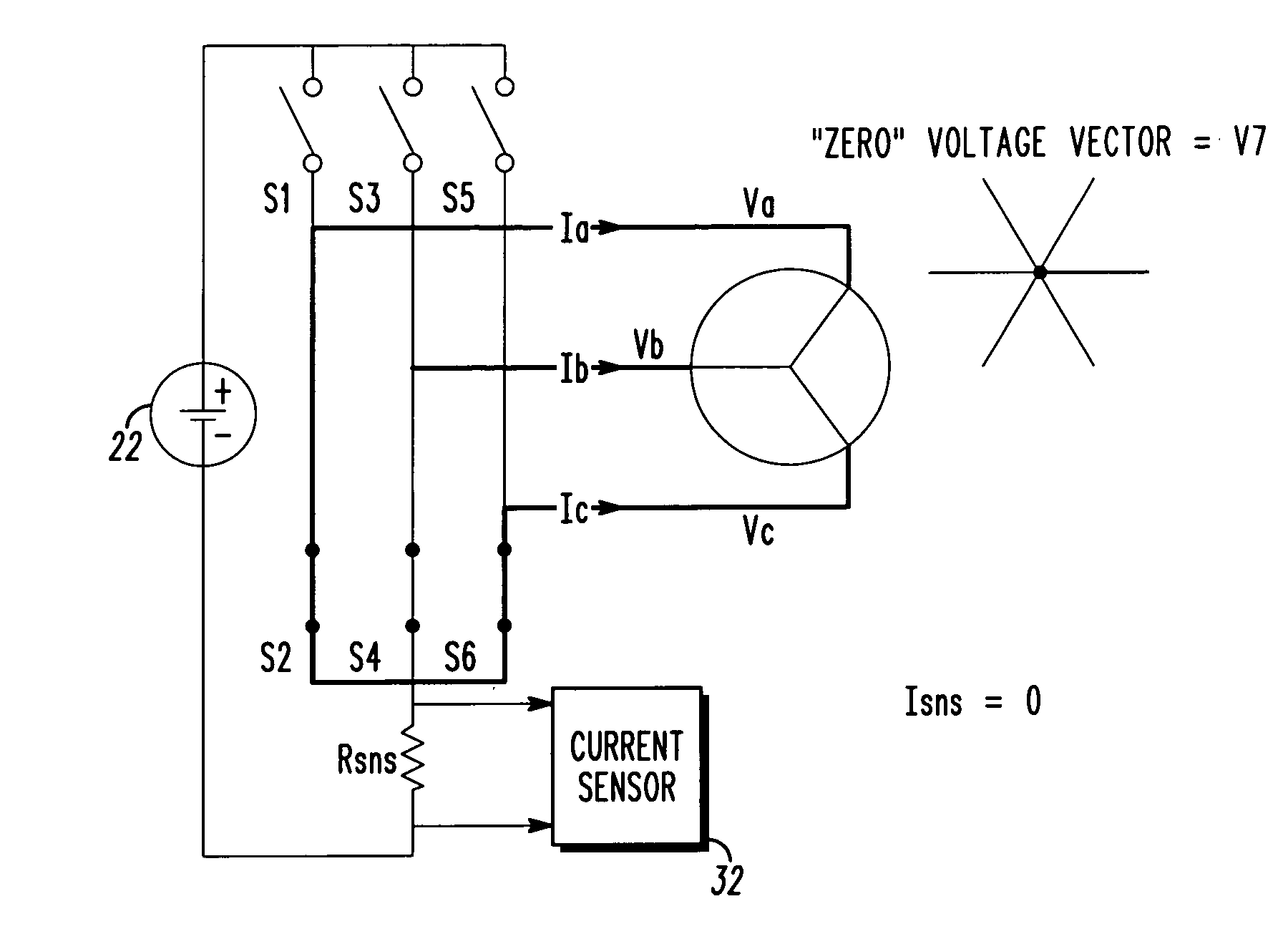
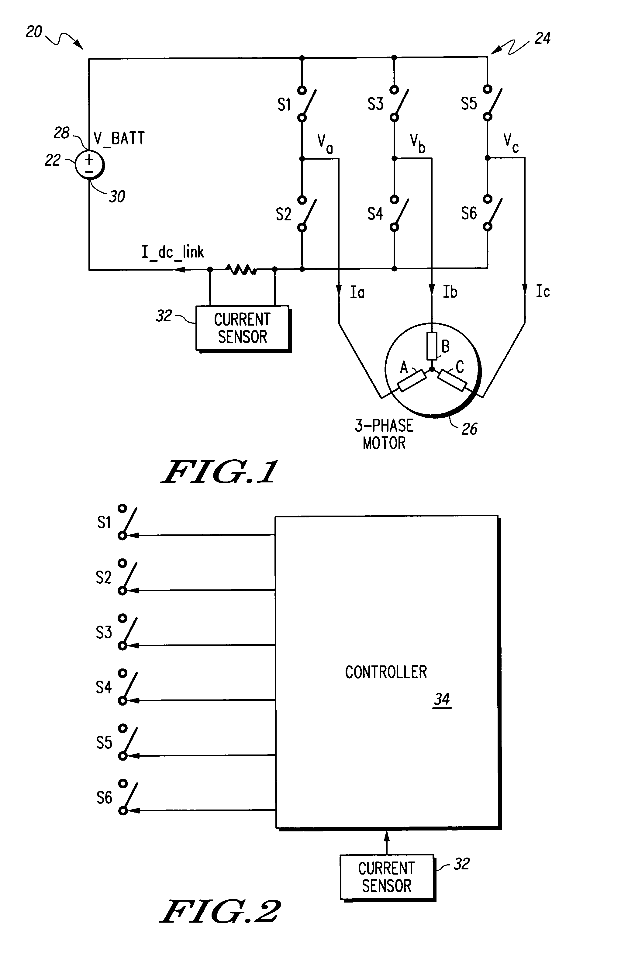
[0021]What is described is an improved procedure for measuring the electric current flowing through each phase of a three-phase device in a system, during damping mode, using a single external current sensor. Advantageously, no additional hardware is needed to implement the invention. Three-phase motors, such as permanent magnet synchronous motors, may be used as part of a powered mechanical system. The present invention, however, is not limited to three-phase motors and may be applicable to other three-phase devices or even multi-phase devices.

[0022]It is possible for the powered mechanical systems to exhibit a lightly-damped resonant response within a specific frequency region (e.g. 5-10 Hz) due to the mechanical properties of the system and the closed loop response of the controller. However, it is desirable that the closed-loop control system remain stable for all possible mechanical disturbances. If a mechanical disturbance is encountered which is in the frequency range where a...


PUM


Abstract

While a PWM-controlled, FET-switched three-phase motor is operating in a mechanical damping mode, a single current sensor is used to measure current in the motor. When mechanical feedback into the motor exceeds a predetermined threshold, a bank of the FET switches can be closed to provide damping of the mechanical feedback. This causes currents to circulate within the motor, which an external single current sensor cannot measure to determine current load or when the mechanical feedback is no longer a problem. The present invention periodically switches selected switches necessary to sample the current in at least one phase of the motor to determine when the mechanical feedback into the motor is no longer a problem, while preferably also maintaining an average zero voltage vector.

Description

FIELD OF THE INVENTION[0001]This invention in general relates to three-phase power devices (such as three-phase motors) and, more particularly, to an improved procedure for measuring the currents in each phase via a single current sensor for damping control and motor braking.BACKGROUND OF THE INVENTION[0002]A three-phase motor (such as a permanent magnet synchronous motor and induction motor) can be used in many applications to provide power assistance to mechanical systems. It is known to control the phase windings in a three-phase motor using pulse width modulated signals. The pulse width modulated signals are applied to an inverter or a series of switching devices that connect the phase windings of the motor to either a positive or negative terminal of a direct current (DC) power supply, such as a battery. This inverter consists of three switches in an upper bank and three switches in a lower bank.[0003]To adequately control the motor, it is necessary to measure the current flowi...

Claims


Application Information

Patent Timeline
Patent Type & Authority Patents(United States)
IPC IPC(8): G01R31/34G05B19/00H02M1/00H02P23/00H02P3/18H02P3/22H02P7/00H02P21/00H02P23/04
CPCH02P3/22H02P23/04H02M2001/0009H02M7/5395H02M1/0009
Inventor O'GORMAN, PATRICK A.REPPLINGER, SCOTT W.
Owner CONTINENTAL AUTOMOTIVE SYST INC
Why Eureka
Try Eureka