Removal of spurious aircraft detections on weather radar

a technology of weather radar and aircraft detection, applied in the direction of climate sustainability, instruments, measurement devices, etc., can solve the problems of difficult weather decision-making and worse problems, and achieve the effects of avoiding pilot confusion and errors, improving performance, and low cos

Active Publication Date: 2008-08-26
ROCKWELL COLLINS INC
View PDF9 Cites 56 Cited by
  • Summary
  • Abstract
  • Description
  • Claims
  • Application Information

AI Technical Summary

Benefits of technology

[0016]It is an advantage of the present invention to provide a weather radar system to detect and remove spurious aircraft with several embodiments disclosed that can be used individually or in combination to improve performance.
[0017]It is an advantage of the present invention to provide a weather display with the spurious aircraft images removed to avoid pilot confusion and errors.
[0018]It is a feature of the present invention to provide reliable removal of spurious aircraft from a weather radar display.
[0019]It is a feature of the present invention to provide low cost methods of removal of spurious aircraft from a weather radar display.

Problems solved by technology

Flight hazards due to weather conditions are primarily the result of precipitation and turbulence.
Newer radars use longer transmitter pulse widths that make the problem worse since the length of the radar return from aircraft on the radar display is not substantially different from the radar return length as produced by a small area weather feature.
Having a weather display with spurious aircraft displayed is undesirable since it may lead to difficult decision making about the weather and the spurious aircraft motion.

Method used


Image

  • Removal of spurious aircraft detections on weather radar
  • Removal of spurious aircraft detections on weather radar
  • Removal of spurious aircraft detections on weather radar

Examples


first embodiment

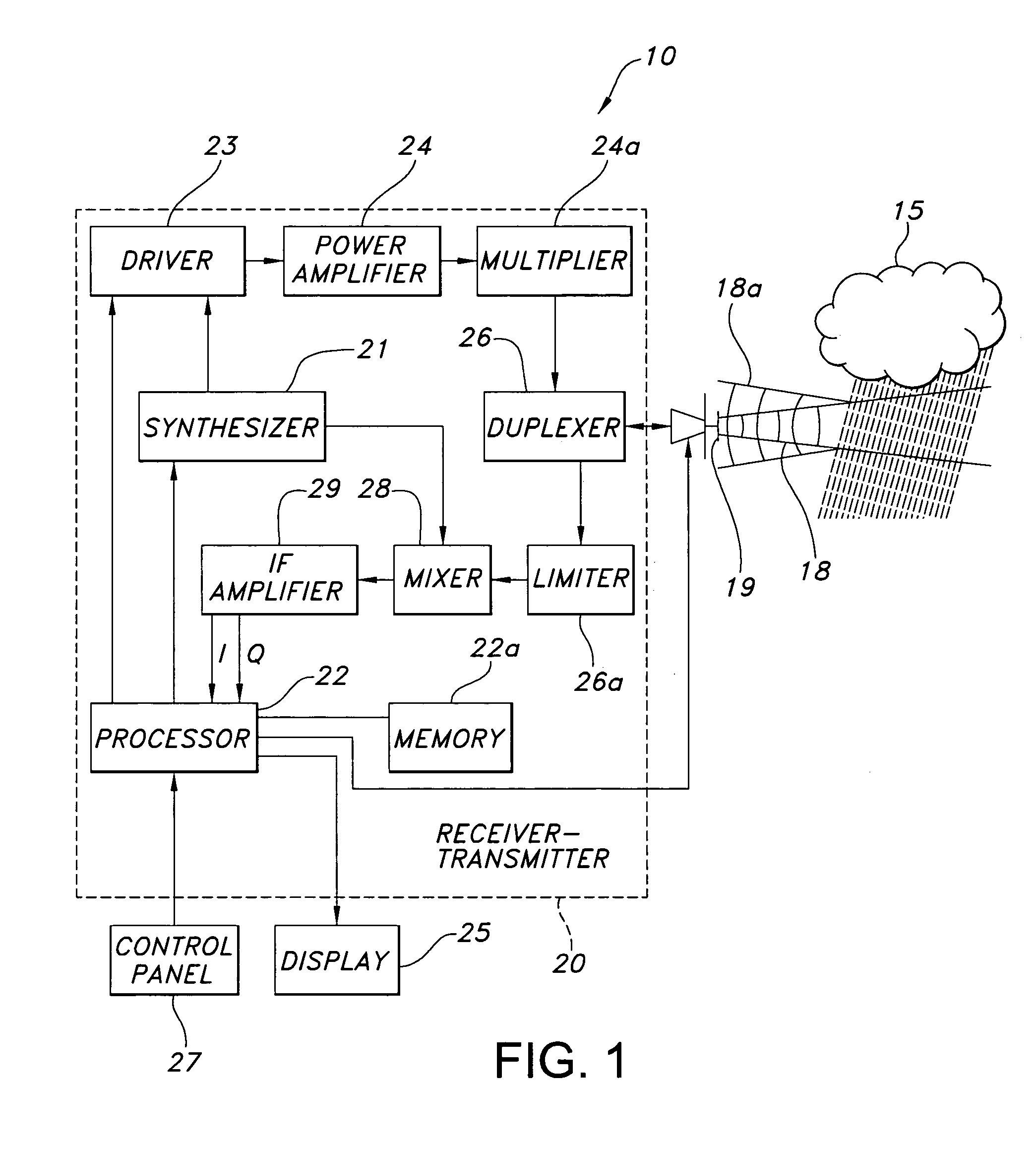
[0058]In the present invention shown in FIG. 6, radar return length differentiation is used to separate and edit out shorter returns from the spurious aircraft 35 from longer length weather returns in the weather radar system 10 of FIG. 1. The weather radar system 10 of FIG. 1 may intermix high resolution pulses 61, such as short pulses or compressed long pulses, and long pulses 60 as shown in FIG. 6 while scanning a weather system such as thunderstorm 15. The weather radar system 10 may transmit just the high resolution pulses 61. The receiver-transmitter 20 transmits the high resolution pulses 61 that result in high resolution return pulses 61a from the spurious aircraft 35 and high resolution return pulses 61b from the thunderstorm 15. High resolution return pulses 61a from high resolution pulses 61 may not be used for radar display because of low loop gain due to bandwidth but may still be used to identify spurious aircraft 35. The high resolution return pulses 61a from the spur...

third embodiment

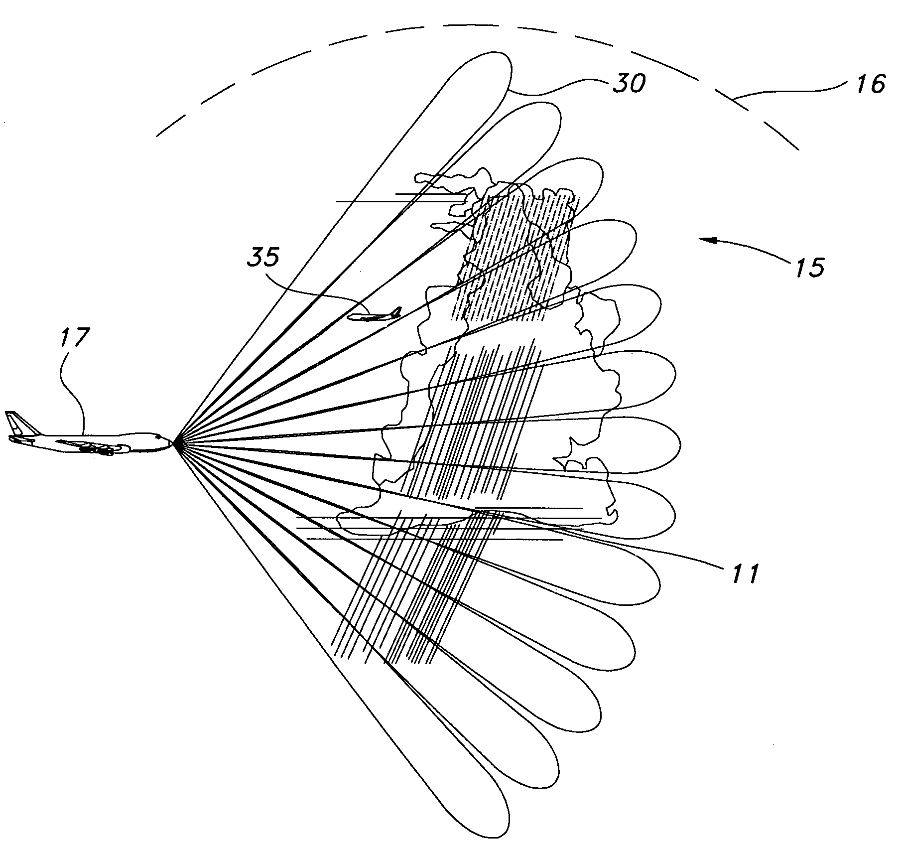
[0062]In the present invention, areas of radar returns from the spurious aircraft 35 that are eliminated from the weather display 25 by using any of the other methods described herein can be tracked into regions where neither the original nor other methods provide detection. The spurious aircraft 35 can continue to be removed by tracking the spurious aircraft 35 into regions where it cannot be detected. As an example in FIG. 8, the antenna 19 on an aircraft 17 points the upper radar beam 30 down to receive return pulses from the weather system 15 and also receives return pulses in the upper radar beam 30 field of view. The processor 22 determines if the return pulses in the upper radar beam 30 field of view are from the spurious aircraft 35 by the size and extent of a vertical gradient return compared to the pulse returns from the weather system 15. The processor 22 identifies the pulses returns as being from the spurious aircraft 35 and accumulates tracking data of the spurious air...

fourth embodiment

[0064]In the present invention, radar returns from the spurious aircraft 35 are tracked that allow detection and removal of the spurious aircraft 35 in certain relative geometries created by the motion and position of the spurious aircraft 35 relative to the weather system 15. In FIG. 9 consider the spurious aircraft 35 moving across the weather radar system 10 field of view 62 in front of the weather system 15. Since both the radar equipped aircraft 17 and the spurious aircraft 35 are in an environmental airflow, the tracked movement of the spurious aircraft 35 across the radar's field of view 62 produces return pulses that are not like return pulses from weather system 15. The relative geometries that allow detection include motion of the spurious aircraft 35 across the radar's field of view with horizontal, climbing or descending aircraft motion. Motion of the spurious aircraft 35 produces returns that are different than the returns from the weather system 15 thereby allowing ide...


PUM


Abstract

A weather radar detects and removes spurious aircraft from a weather radar display by using one of the methods of differentiating radar return length, estimating a vertical gradient of reflectivity, tracking radar returns into regions that are eliminated from the weather display to provide differentiation, tracking areas of radar returns that allow detection and removal of the spurious aircraft in relative geometries, differentiating Doppler velocity, and differentiating spectral width. The methods may be used individually or in combination to improve performance.

Description

BACKGROUND OF THE INVENTION[0001]This invention relates to weather radar, spurious aircraft detections, and specifically for removal of spurious aircraft detections from a weather radar display when displaying of such detections is not desired.[0002]Weather radars are known in the art for detecting and displaying severe weather to a crew in an aircraft on a two-dimensional map display showing range, bearing, and intensity of a detected weather system, which may be convective or stratiform in nature. Flight hazards due to weather conditions are primarily the result of precipitation and turbulence. Airborne weather radars have been optimized to detect rain.[0003]As weather radars become more sensitive and hold and process previously sampled state information, other aircraft are being detected and displayed to flight crews when not desired. Newer radars use longer transmitter pulse widths that make the problem worse since the length of the radar return from aircraft on the radar displa...

Claims


Application Information

Patent Timeline
Patent Type & Authority Patents(United States)
IPC IPC(8): G01S13/95
CPCG01S7/292G01S13/953G01S13/106G01S13/28Y02A90/10
Inventor WOODELL, DANIEL L.ROBERTSON, ROY E.DICKERSON, CHARLES J.
Owner ROCKWELL COLLINS INC
Why Eureka
Try Eureka