Capillary electrophoresis apparatus

a capillary array and electrophoresis technology, applied in the direction of fluid pressure measurement, liquid/fluent solid measurement, peptide measurement, etc., can solve the problems of deteriorating fluorescence detection sensitivity and inability of conventional capillary array electrophoresis apparatus to perform such functions, and achieve high sensitivity

Active Publication Date: 2008-09-02
HITACHI HIGH-TECH CORP
View PDF15 Cites 19 Cited by
  • Summary
  • Abstract
  • Description
  • Claims
  • Application Information

AI Technical Summary

Benefits of technology

[0020]It is reported that a buffering cistern is provided in the lower part of the end face of the edge portion of the capillary or a gel plate and fluorescence is detected via the preceding buffering cistern, as described in the foregoing. In such a case, however, the capillary or the gel plate is filled with gel in advance, thus a means for injecting gel, i.e. polymer, has not been needed. Further, in the case of sequential automatic analysis having a polymer injection means, since the structure of FIG. 2 is employed, the end detection has been impossible. This invention is to provide a novel means for providing compatible sequential automatic analysis with the end detection at the time of utilizing the structure having the polymer injection means. Accordingly, a high-throughput capillary array electrophoresis apparatus can be provided, which can measure a number of capillaries at a time with high sensitivity and have capable of analyzing sequentially a number of samples automatically.

Problems solved by technology

However, a conventional capillary array electrophoresis apparatus cannot perform functions for such demands.
However, since material of the polymer filling block 400 is made of acryl resin, problems are caused, in which fluorescence and scattered light irradiated from acryl resin become back light and fluorescence detection sensitivity is deteriorated.

Method used


Image

  • Capillary electrophoresis apparatus
  • Capillary electrophoresis apparatus
  • Capillary electrophoresis apparatus

Examples


first embodiment

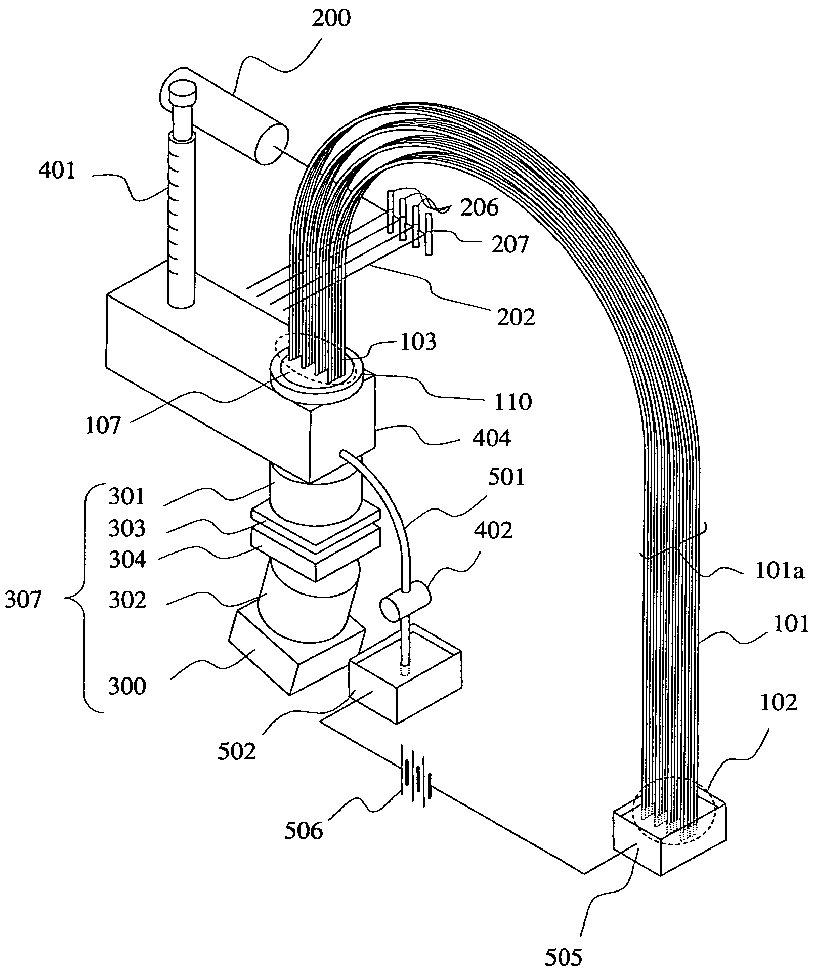
[0046]FIG. 4 illustrates an automatic capillary array electrophoresis apparatus as an example. This example explains the way for analyzing electrophoresis of 20 capillaries at a time. 20 capillaries are bunched and form capillary arrays 101a. Each capillary 101 is made of quartz, and a polyimide coat is formed in the external surface of each capillary 101, which has a total length of 40 cm, an external diameter of 360 μm, and an internal diameter of 50 μm. Here, a capillary coated with fluorine resin can be used instead of the capillary coated with polyimide. In each capillary 101, a start edge portion 102 is a side of installing samples and an end edge portion 103 is a side of migrating and liquating out samples in the capillary by electrophoresis. A laser illumination position is a position which is 30 cm (10 cm from the end face of the end edge portion 103) from the end face of the start edge portion 102 of each capillary 101, and the polyimide coating of its capillary portion is...

second embodiment

[0059]The object of the present embodiment is to make real easy operability of cleaning and changing the detection window by dividing the polymer filling block 404 of FIG. 4 into 2 parts of a portion having the syringe 401 and a portion having the capillary array head 107, etc.

[0060]In the structure of the apparatus, only the structure of the polymer filling block 404 is different from the case of the first embodiment, but the structure other than this element is the same as the case of the first embodiment. The structure of a polymer filling block 406 and a detection block 407 of installing a capillary array head 107 of the present embodiment is indicated in FIG. 8. The capillary array head 107 is connected to the detection block 407 using the screw 110 and the ferrule 111. A method of connecting the capillary array head 107 to the detection block 407 and adjustment of the position of connecting the capillary array head 107 are the same as the first embodiment. The detection block ...

third embodiment

[0064]In embodiments 1 and 2, if electrophoresis is performed by applying voltage to each capillary 101, Joule heat is generated inside the capillary 101. In the capillary array head 107 as indicated in FIG. 5, since the capillary 101 is enclosed by the adhesive agent 108, the cylindrical fixing jig 106, the polymer filling block 404 or detection block 407, effectiveness of releasing Joule heat generated inside the capillary is low. Thus, the vicinity of the capillary array head 107 becomes high temperature. As a result, the polymer solution inside the capillary 101 near the capillary array head 107 and the polymer solution of the duct formed between the detection window 306 and the detection flat surface 109 are boiled, thus bubbles may be produced. If such a condition is caused, electrophoresis performance is degraded outstandingly and further fluorescence cannot be made. Accordingly, the object of the present embodiment is to remove effectively Joule heat generated in the capilla...


PUM

PropertyMeasurementUnit
distanceaaaaaaaaaa
distanceaaaaaaaaaa
internal diameteraaaaaaaaaa

Abstract

A capillary array electrophoresis which can measure fluorescence of a number of capillaries at a time with high sensitivity and can automatically analyze a sample sequentially. An end edge as a sample dissolution edge of a number of capillaries is connected to a polymer filling block having a mechanism of filling the polymer as an isolation medium inside a capillary. Fluorescence irradiated from an edge surface of an end edge portion of the capillary is detected through a detection window in which distance between an external surface and a detection surface is smaller than focal distance of an optical lens closest to a detection flat surface.

Description

CLAIM OF PRIORITY [0001]The present application claims priority from Japanese application JP 2003-107193 filed on Apr. 11, 2003, the content of which is hereby incorporated by reference into this application.FIELD OF THE INVENTION [0002]The present invention relates to a technical field for an apparatus for separating and analyzing biomaterial such as DNA, RNA, or protein, and in particular to a technical field for capillary array electrophoresis apparatus using plural capillaries especially for sample separation column and using a fluorescence detection method as a sample measurement method.BACKGROUND OF THE INVENTION[0003]Electrophoresis is a basic method for separating and analyzing DNA, RNA, etc. Conventionally, a slab gel electrophoresis apparatus using slab gel having gel between two glasses as electrophoresis separation columns has been utilized. As large scale separation and analysis represented by Human Genome Project become important, however, high speed and high throughpu...

Claims


Application Information

Patent Timeline
Patent Type & Authority Patents(United States)
IPC IPC(8): G01N27/453G01N27/447
CPCG01N27/44782G01N27/44721
Inventor SAKAI, TOMOYUKIANAZAWA, TAKASHI
Owner HITACHI HIGH-TECH CORP
Why Eureka
Try Eureka