
Reference timing signal apparatus and method

Active Publication Date: 2008-09-09
APPLE INC
View PDF11 Cites 40 Cited by
  • Summary
  • Abstract
  • Description
  • Claims
  • Application Information

AI Technical Summary

Benefits of technology

[0014]It is an object of the present invention to provide an improved reference timing signal apparatus and method for providing a timing output signal.
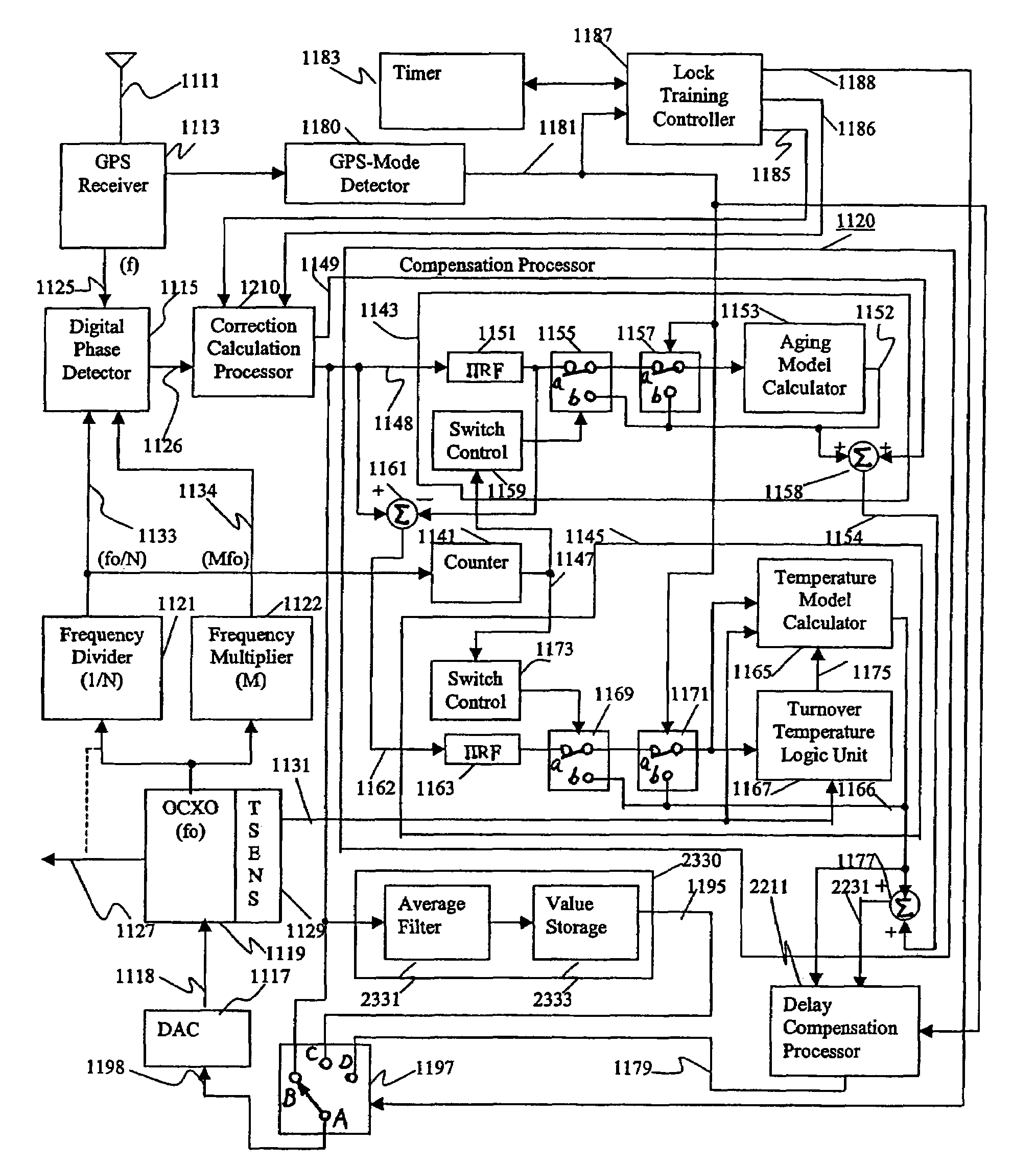
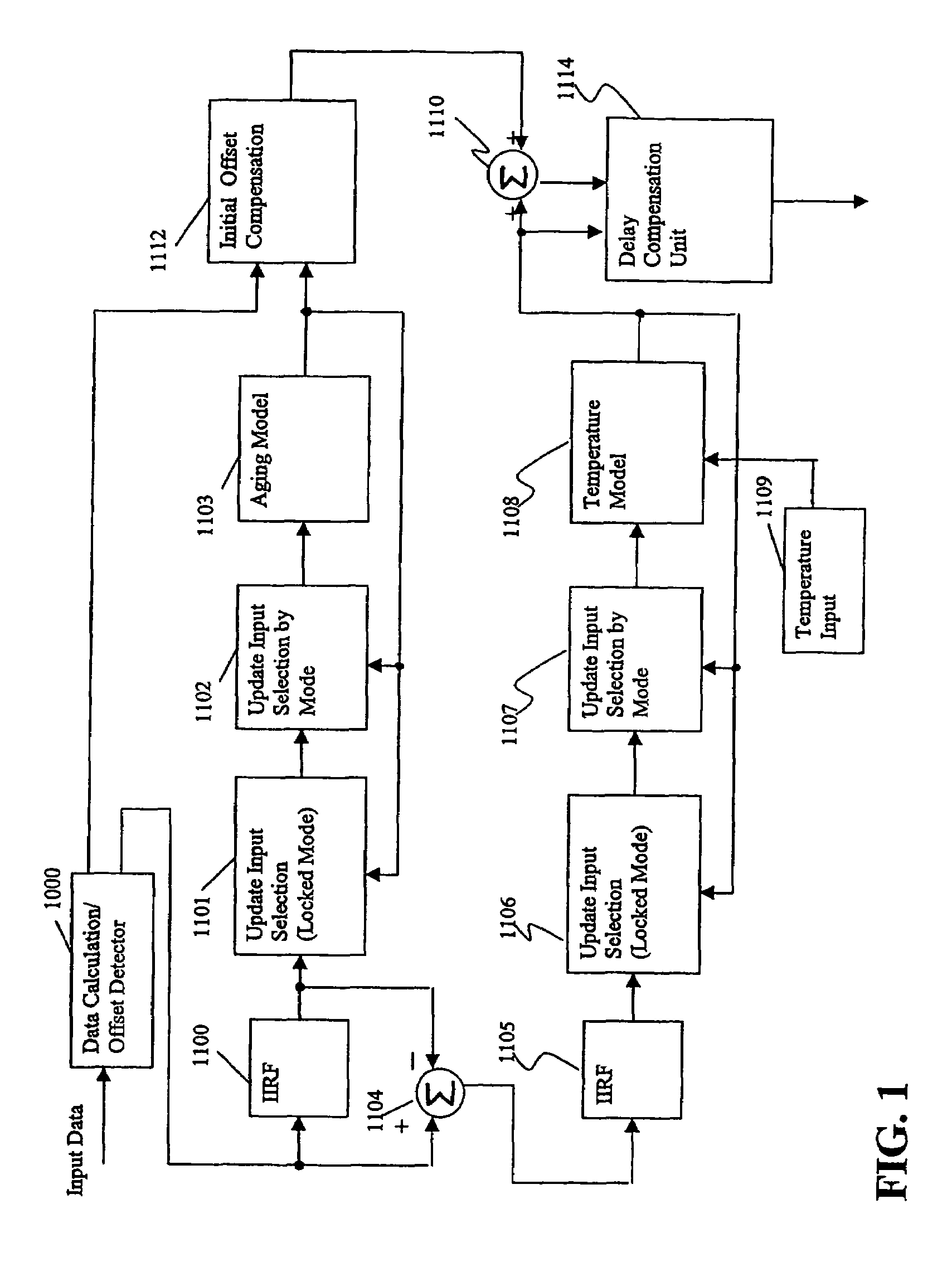
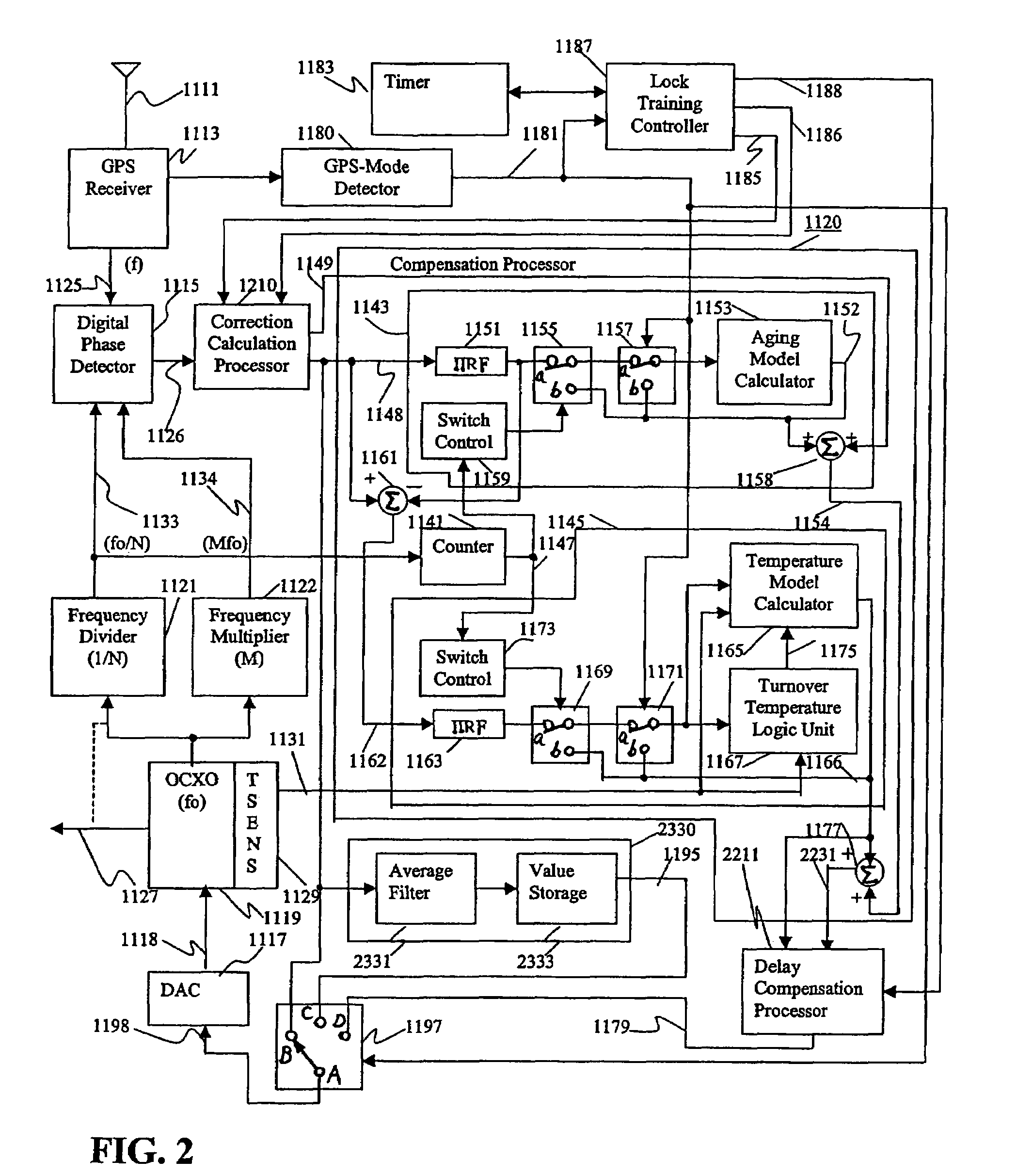
[0023]In the reference timing signal apparatus, the compensation unit compensates the time delay resulted from the pre-processing filters and thus, the tracking of the reference timing signal apparatus is improved.
[0024]In a case where the reference timing signal apparatus is applied to a base station, for example, it improves current GPS-based clock stability during holdover by better estimating and compensating for the performance of a crystal used to generate a clock signal during the holdover period. Also, it improves the clock stability during holdover based in other satellite systems, e.g., GLONASS and Galileo.
[0034]In the reference timing signal apparatus, no pre-processing filters are used and thus, no time delay compensation is necessary. Also, the updating of the model characteristics is dynamically and adaptively changed and thus, the reference timing signal apparatus's tracking is improved.

Problems solved by technology

The oscillator has aging and temperature characteristics resulting in variation in oscillation frequency.

Method used


Image

  • Reference timing signal apparatus and method
  • Reference timing signal apparatus and method
  • Reference timing signal apparatus and method

Examples


Embodiment Construction

[0068]In the following detailed description of sample embodiments of the invention, reference is made to the accompanying drawings which form a part hereof, and in which is shown by way of illustration specific sample embodiments in which the invention may be practiced. These embodiments are described in sufficient detail to enable those skilled in the art to practice the present invention, and it is to be understood that other embodiments may be utilized and that logical, mechanical, electrical, and other changes may be made without departing from the scope of the present invention. The following detailed description is, therefore, not to be taken in a limiting sense, and the scope of the present invention is defined only by the appended claims.

[0069]The present invention is applicable to a computer algorithm which adaptively models the multiple frequency dependent characteristics in relation to an oscillator following a “training period”. The subsequent model predicts the future f...


PUM


Abstract

A reference timing signal apparatus with a phase-locked loop has a computer algorithm which adaptively models the multiple frequencies of an oscillator following a training period. The oscillation frequency of the oscillator is controlled in response to a phase detector output. The computer algorithm processes the control signal applied to the oscillator. The computer algorithm updates the characteristics of the model relating to the aging and temperature of the oscillator, using for example, a Kalman filter as an adaptive filter. By the algorithm, the subsequent model predicts the future frequency state of the oscillator on which it was trained. The predicted frequency of the model functions as a reference to correct the frequency of the oscillator in the event that no input reference timing signal is available. In a case of using pre-processing infinite impulse response filters (IIRFs) before the adaptive processor, the time delay caused by the filters are compensated after the adaptive processor. Without pre-processing IIRFs, aging and temperature update rates are adaptively controlled by dynamically changing the rates depending upon the loop condition to achieve a wider tracking bandwidth. With the model updating algorithm, oscillators of low stability performance may be used as cellular base station reference oscillator.

Description

FIELD OF THE INVENTION[0001]The present invention relates to a reference timing signal apparatus and method for providing a timing output signal. The reference timing signal apparatus is applicable to a cellular telephone base station, for example. The present invention is also applicable to reference signal or clock signal generators in other types of apparatus, for example, optical transport networks.BACKGROUND OF THE INVENTION[0002]A known cellular telephone system is a Code Division Multiple Access (CDMA) system. The CDMA wireless phone system allows multiple cellular phone users to share the same frequency spectrum, and uses a generated noise carrier with a different and essentially orthogonal instance of the noise carrier assigned to each mobile unit within a cell. The base station receiver in a CDMA station correlates the received signal from a mobile unit with the desired noise carrier, extracting the transmitted digital signal with a sufficient signal-to-noise ratio to achi...

Claims


Application Information

Patent Timeline
IPC IPC(8): H03D1/00
CPCH03L7/14H03L1/00
Inventor NICHOLLS, CHARLESCARLETON, GREGORYBEAUDIN, STEVE
Owner APPLE INC
Learn More