All-digital phase-locked loop for a digital pulse-width modulator

a digital pulse width modulator and phase-locked loop technology, applied in the direction of pulse automatic control, angle demodulation by phase difference detection, electrical equipment, etc., can solve the problems of external components not only costing the system manufacturer, but also adding to the cost of the integrated circuit realizing the pll

Active Publication Date: 2008-09-16
TEXAS INSTR INC
View PDF6 Cites 19 Cited by
  • Summary
  • Abstract
  • Description
  • Claims
  • Application Information

AI Technical Summary

Benefits of technology

[0019]It is a further object of this invention to provide such a circuit that does not require external passive filter components, and that attains other advantages of digital circuitry such as improved speed of design and design verification, scalability and portability to other applications and new manufacturing processes, reduced noise sensitivity, and reduced cost of manufacture by eliminating large analog circuits such as band-gap reference circuits and charge pumps.
[0021]The present invention may be implemented into an all-digital phase-locked loop circuit, including a digital controlled oscillator based on a pair of digitally controlled delay cells, that effectively implement a combined sinc filter and comb filter into the operation of converting a digital signal to a continuous waveform. The delay of the delay cells is based on the phase difference between a feedback signal and the reference clock signal, and preferably includes both coarse and fine control of the delay. Because of the inclusion of the combined sinc and comb filters in the digital controlled oscillator, the loop filter can be realized as a simple first order digital filter.

Problems solved by technology

These external components are not only costly to the system manufacturer, but also add to the cost of the integrated circuit realizing the PLL, by requiring additional integrated circuit chip and package space for connections to the external components.

Method used


Image

  • All-digital phase-locked loop for a digital pulse-width modulator
  • All-digital phase-locked loop for a digital pulse-width modulator
  • All-digital phase-locked loop for a digital pulse-width modulator

Examples


Embodiment Construction

[0032]The present invention will be described in connection with its preferred embodiment, namely as implemented into a digital phase-locked loop in a digital audio system. Such an implementation is described in this specification because it is contemplated that the benefits of this invention are particularly valuable in such an application. However, it is also contemplated that this invention may provide similar benefits in a wide range of applications and architectures. As such, it is to be understood that the following description is provided by way of example only, and is not intended to limit the true scope of this invention as claimed.

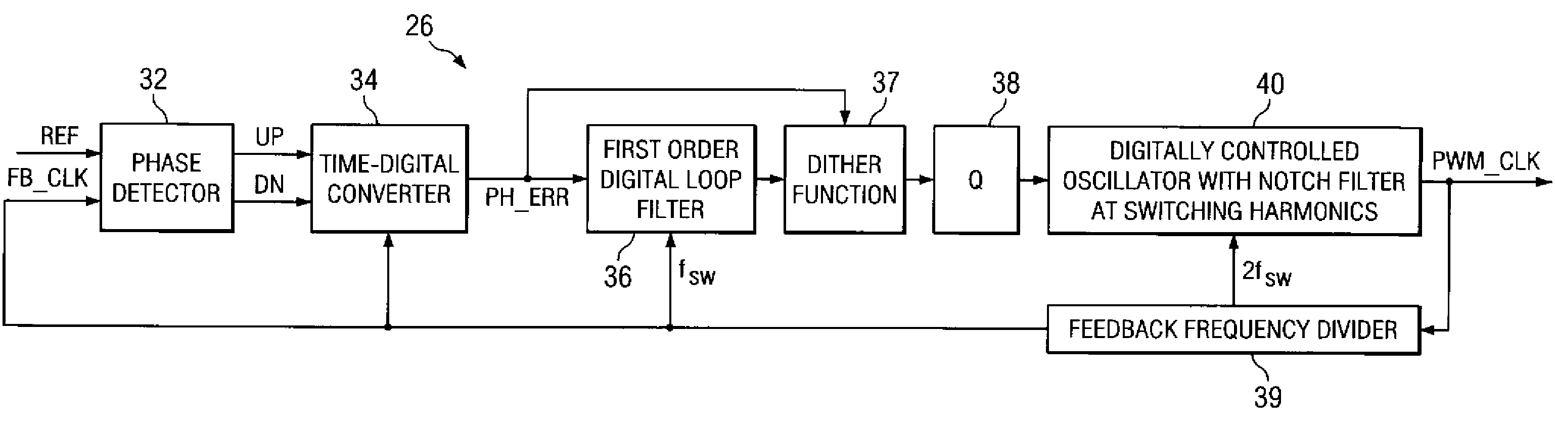
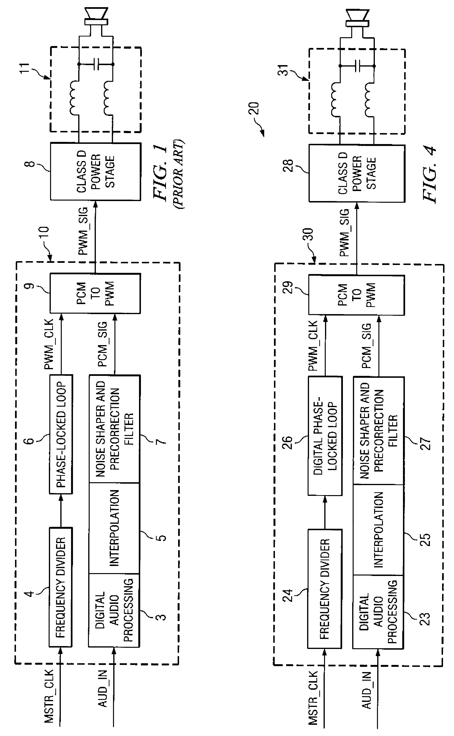
[0033]Referring now to FIG. 4, digital audio system 20 constructed according to the preferred embodiment of the invention will now be described. In the example of FIG. 4, only a single output channel (i.e., represented by speaker SPKR) is illustrated; it will be understood by those skilled in the art having reference to this specification, of cou...


PUM


Abstract

A digital audio system including a digital phase-locked-loop circuit for generating a pulse-width-modulation (PWM) clock signal, applied to a pulse-code-modulation to pulse-width-modulation converter, is disclosed. The digital phase-locked loop includes a phase detector for measuring phase error between a reference signal and a feedback signal. A digital version of the phase error, after filtering by a loop filter, is converted to a digital delay control word that is sampled at twice its frequency. Successive samples of the delay control word control the propagation delay of first and second delay cells in an oscillator. The use of successive samples at substantially twice the frequency of change of the delay control word effectively realizes the sum of a sinc filter and a comb filter, which greatly suppresses the effects of jitter in the reference signal to the digital phase-locked loop.

Description

CROSS-REFERENCE TO RELATED APPLICATIONS[0001]Not applicable.STATEMENT REGARDING FEDERALLY SPONSORED RESEARCH OR DEVELOPMENT[0002]Not applicable.BACKGROUND OF THE INVENTION[0003]This invention is in the field of phase-locked loop circuits, and is more specifically directed to such circuits as used in digital audio systems involving class D output amplification driven by pulse-width-modulated drive signals.[0004]In recent years, digital signal processing techniques have become prevalent in many electronic systems. Tremendous increases in the switching speed of digital circuits have enabled digital signal processing to replace, in large part, analog circuits in many applications. For example, the sampling rates of modern digital signal processing are sufficiently fast that digital techniques have become widely implemented in audio electronic applications.[0005]Digital techniques for audio signal processing now extend to the driving of the audio output amplifiers. A new class of amplifi...

Claims


Application Information

Patent Timeline
Patent Type & Authority Patents(United States)
IPC IPC(8): H03L7/093
CPCH03L7/0995H03L7/0991H03L7/093H03L7/089
Inventor RISBO, LARSSHANKAR, ASITANGILIVELIL, JOSEY GEORGE
Owner TEXAS INSTR INC
Why Eureka
Try Eureka