
Ignition system of an internal combustion engine

a technology of internal combustion engine and ignition system, which is applied in the direction of combustion-air/fuel-air treatment, automatic control of ignition, machines/engines, etc., can solve the problems of inability to achieve the effect of improving the quality of combustion process, improving combustion efficiency, and small dimensions

Inactive Publication Date: 2008-10-07
ROBERT BOSCH GMBH
View PDF23 Cites 3 Cited by
  • Summary
  • Abstract
  • Description
  • Claims
  • Application Information

AI Technical Summary

Benefits of technology

The present invention provides an ignition system for an internal combustion engine that does not require a spark plug or complex moving parts. The system uses oxygen radicals to enrich the process space and improve combustion quality. The lower temperatures achieved through the use of oxygen radicals allows for better ignition and reduced ignition delay time. The system is suitable for very lean fuel / air mixtures and can be easily integrated into existing designs of internal combustion engines. The device for enriching the process space with oxygen radicals includes an oxygen ion conductor made of ceramic material.

Problems solved by technology

The quality of the combustion process is basically limited when a spark is used as the combustion triggering pulse since high temperatures prevail here by the nature of the system and the ignition point is difficult to influence.
The concept of what is known as compression ignition represents an alternative which is, however, usually very complex with regard to its design layout.

Method used


Image

  • Ignition system of an internal combustion engine
  • Ignition system of an internal combustion engine
  • Ignition system of an internal combustion engine

Examples


Embodiment Construction

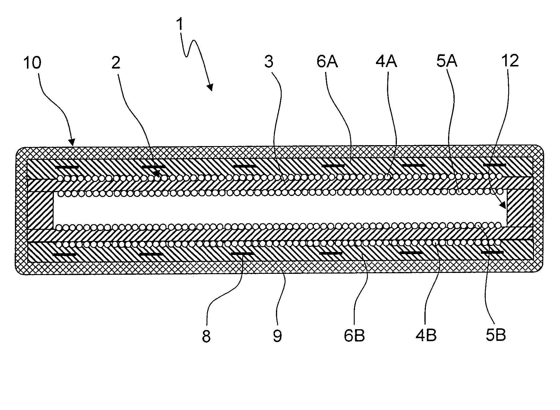
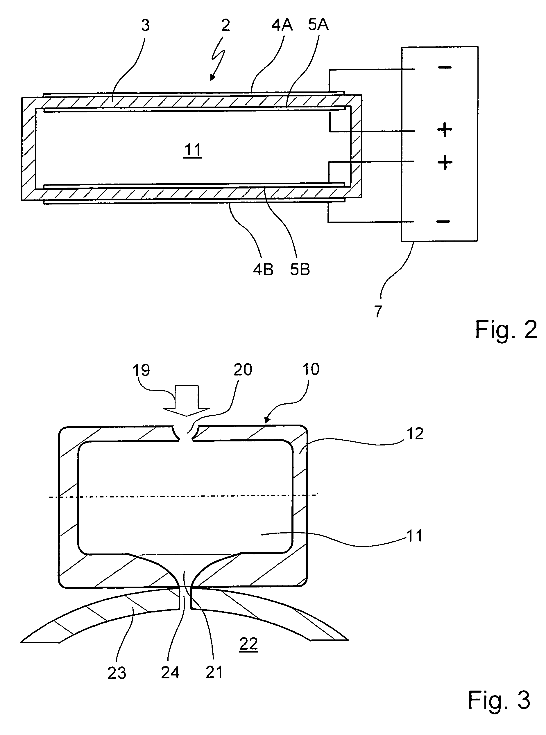
[0020]With reference to FIG. 1, a device 1 for igniting a jet of a fuel / air mixture for combustion in an internal combustion engine of a motor vehicle is shown which has a chamber 10 which encloses a process space 11 having a wall 12.

[0021]Device 1 is designed for igniting the fuel / air mixture with the aid of oxygen radicals and has, for this purpose, a device 2 for adding oxygen radicals to process space 11 of chamber 10. Device 2 includes an oxygen ion conductor 3 which in the present case is formed frame-like on wall 12 of chamber 10 and represents an innermost layer of wall 12 of chamber 10 having a multilayer design.

[0022]Oxygen ion conductor 3 is in the present case made from yttrium (Y)-doped zirconium dioxide (ZrO2). Controlled doping of ceramics such as zirconium dioxide makes it possible to create oxygen ion vacancies and to transform the ceramic, doped in this way, into a very good electrical oxygen ion conductor which in turn forms a solid electrolyte.

[0023]In the exempl...


PUM


Abstract

An ignition system of an internal combustion engine, of a motor vehicle in particular, having at least one device for igniting a jet of a fuel / air mixture which has a chamber enclosing a process space in which the ignition of the fuel / air mixture takes place. The chamber has a device for enriching the process space with oxygen radicals.

Description

FIELD OF THE INVENTION[0001]The present invention relates to an ignition system of an internal combustion engine having a device for igniting a jet of a fuel / air mixture.BACKGROUND INFORMATION[0002]Early designs of ignition systems including jet ignition sources for motor vehicles having internal combustion engines are described in U.S. Pat. Nos. 3,092,088; 3,230,939; and 4,250,852, for example. Refinements of such an ignition system having a precombustion chamber and often two or more jet ignition sources are described in U.S. Pat. Nos. 4,361,122; 4,416,228; 4,924,828, and 5,522,357, for example.[0003]The feature common to all these ignition systems having what is referred to as jet ignition (JI) is that a spark is required for initializing the combustion of fuel in a combustion chamber of the internal combustion engine; a spark plug must be provided for spark generation.[0004]The quality of the combustion process is basically limited when a spark is used as the combustion triggeri...

Claims


Application Information

Patent Timeline
Patent Type & Authority Patents(United States)
IPC IPC(8): F02M57/06F02B51/00F02P23/00
CPCF02M27/02F02M27/04F02P5/045F02P13/00F02P19/00
Inventor LINDNER, FRIEDERIKEEISELE, ULRICHAHMED, JASIMKOJIC, ALEKSANDARHATHOUT, JEAN-PIERRE
Owner ROBERT BOSCH GMBH
Learn More