Method and system of bidirectional data transmission and reception

a data transmission and reception technology, applied in the direction of data switching networks, synchronisation signal speed/phase control, duplex signal operation, etc., can solve the problems of slow rise or fall time of input signal at home station, delay variation, and receiver inability to compare them properly, so as to achieve higher speed operation and increase the operating frequency. , the effect of increasing the operating frequency

Inactive Publication Date: 2008-10-21
HITACHI LTD
View PDF10 Cites 3 Cited by
  • Summary
  • Abstract
  • Description
  • Claims
  • Application Information

AI Technical Summary

Benefits of technology

[0018]With rapid popularization of the Internet in recent years, information-processing devices such as computers and network devices such as routers are required to operate at higher speed. To achieve higher speed operation of these devices, means for increasing operating frequencies or extending bit width have been explored. Communication devices, e.g., ASICs and LSIs, used in the information processing devices and network devices are designed to operate faster and faster and provided with increasing numbers of pins.
[0019]However, it is desirable to use less pins in the communication devices for cost reduction. Accordingly, the above-described simultaneous bi-directional device can be applied to reduce the number of data signal pins provided on the semiconductor communication device by half. The problems described above, however, needs to be solved to effectively implement the simultaneous bi-directional data transfer technology.

Problems solved by technology

However, such a situation frequently occurs in data transfer operations as illustrated in FIG. 3 unless specific precautions are taken.
This causes a delay variation, e.g., a temporary signal processing error during when it is difficult to determine the state of the signal.
Rise or fall time of the input signal at the home station becomes slow as a result of the line resistance and parasitic capacitance of the data line and the input capacitance of the receiver.
Thus, when these two signals with different fall or rise time are input to the differential receiver, the receiver cannot compare them properly due to the jitter in the falling and rising edges.
However, a new problem arises.
This current fluctuation produces simultaneous switching output (SSO) noise.
This noise contributes to the deterioration of the waveform quality of the clock signals.

Method used


Image

  • Method and system of bidirectional data transmission and reception
  • Method and system of bidirectional data transmission and reception
  • Method and system of bidirectional data transmission and reception

Examples


Embodiment Construction

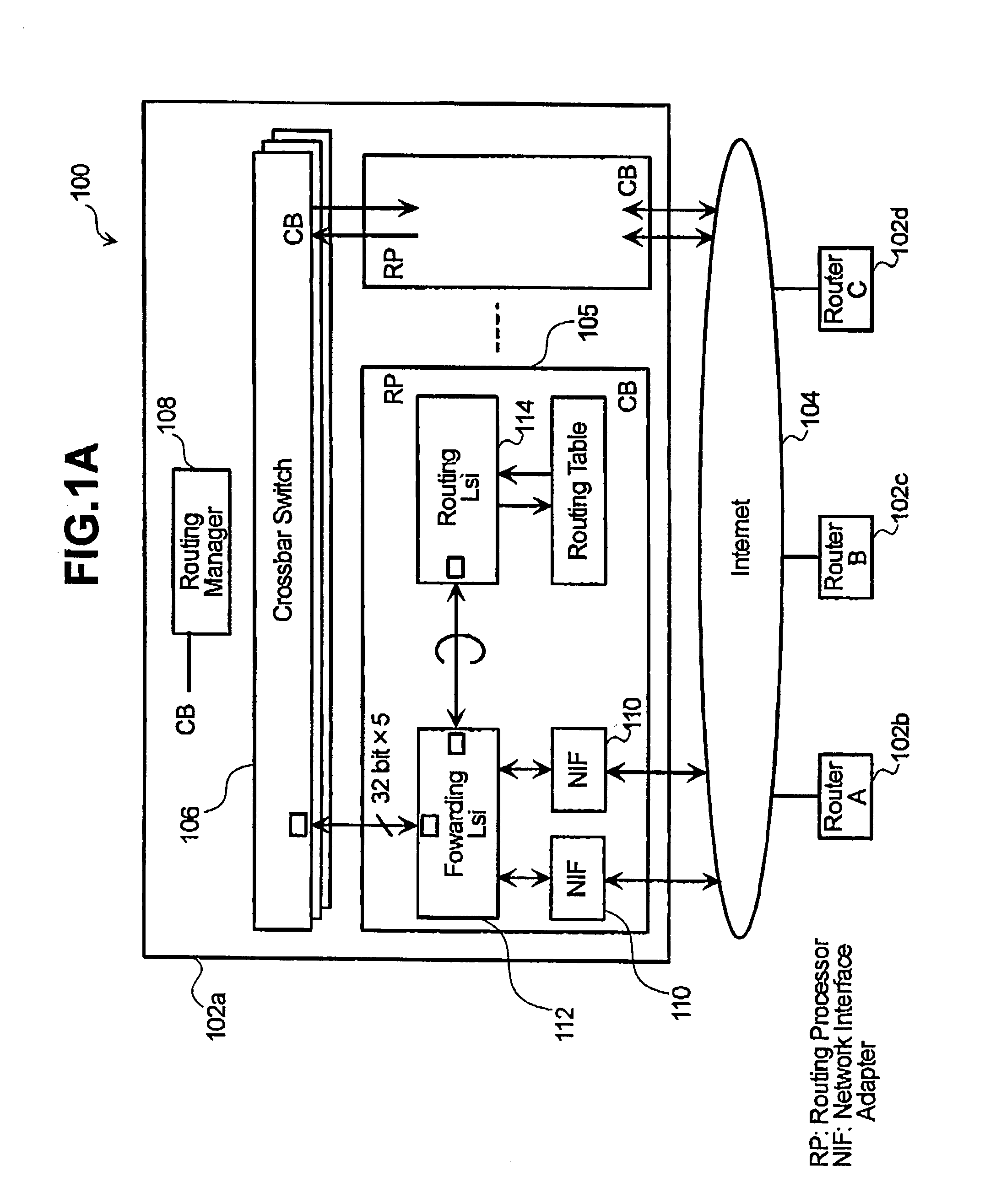
[0040]FIG. 1A illustrates a network system 100 including a plurality of routers 102a-102d and a network 104, e.g., the Internet, linking the routers. The routers may have substantially the same or different configurations. The router 102a is described herein as a representative router.

[0041]The router 102a includes a plurality of routing processors 105 that includes various components used to communicate with other routers 102, a plurality of crossbar switches 106 that transfer data received from one point to another point (e.g., from one routing processor to another routing processor) in the router, and a routing manager 108 that provides information needed by the switches 106 to transfer data.

[0042]The routing processor 105 includes one or more network interface cards or adapters (NTFs) 110 that receive and transmit data to and from the network 104, a forwarding device 112, and a routing device 114. The forwarding device 112 forwards data received from the NIF 110 to the crossbar ...


PUM


Abstract

A simultaneous bi-directional data transferring method includes obtaining a combined signal from a portion of a data line proximate a host device. The combined signal is a signal that combines input and output signals that are being transmitted over the data line. The output signal is a signal transmitted by the host device, and the input signal is a signal transmitted by a remote device. The combined signal is provided to first and second receivers of the host device. A first fixed reference voltage is inputted to the first receiver, and a second fixed reference voltage is inputted to the second receiver. The first and second fixed reference voltages are independent of values of the output signal. A first output receiver signal is outputted from the first receiver using the first fixed reference voltage and the combined signal, and a second output signal is outputted from the second receiver using the second fixed reference voltage and the combined signal. The input signal is reproduced using the first and second output receiver signals. A length of the data line is set to enable the input signal transmitted by the remote device to arrive at an input point of the host device at an integer multiple of a clock cycle.

Description

CROSS-REFERENCES TO RELATED APPLICATIONS[0001]The present application relates to and claims priority from Japanese Patent Application No. 2001-258202, filed on Aug. 28, 2001.BACKGROUND OF THE INVENTION[0002]The present invention relates to simultaneous bi-directional data transfer over data lines.[0003]Data transmission and reception techniques enabling simultaneous bi-directional signal transmission and reception over a single data line have heretofore been known, for example, those described in JP-A-98052-1981 and JP-A-186033-1991. A simultaneous bi-directional data transfer technology involves transmitting and receiving data signals simultaneously over the same data line. In JP-A-98052-1981, the output of a transmitter in a transceiver at one station is connected via a resistor to the data line that carries the output signal to another station having a similar transceiver. In addition, the output signal from the transmitter passes through a resistor, is combined with a base volta...

Claims


Application Information

Patent Timeline
Patent Type & Authority Patents(United States)
IPC IPC(8): H04L5/14H04B3/00H04L25/49H04L7/04H04L12/28H04L25/38
CPCH04L5/14
Inventor BABA, JUNJI
Owner HITACHI LTD
Why Eureka
Try Eureka