Method of evaluating a readout signal, and optical disc apparatus

a technology of optical discs and readout signals, applied in the direction of digital signal error detection/correction, amplitude demodulation, instruments, etc., can solve the problems of generating errors, inability to evaluate a data pattern consisting of spaces and marks with a minimum run-length,

Inactive Publication Date: 2008-10-21
HITACHI-LG DATA STORAGE +1
View PDF5 Cites 10 Cited by
  • Summary
  • Abstract
  • Description
  • Claims
  • Application Information

AI Technical Summary

Benefits of technology

[0018]As mentioned above, the adaptive PRML or compensated PRML methods, in which the target signal level is adaptively varied depending on read signal, are very effective in improving reproduction performance. On the other hand, both MLSE and PRSNR mentioned above are dependent on the PR class, such as PR(1,2,2,1) or PR(1,2,2,2,1), and are compatible with PRML channels with fixed target signal levels.
[0024]The reason why MLSE is incapable of handling a variable target level is that the generation of a target signal adapted to a correct bit sequence as the result of decoding and for an error bit sequence that is shifted by 1 bit from the correct bit sequence, and the calculation of the Euclidean distance from the read signal are based on a fixed target level. Therefore, if it is made possible to carry out the generation of the target signal and the calculation of the Euclidean distance with reference to a target level that is adaptively varied depending on the read signal, Object 1 can be achieved. The former can be realized by extracting a bit sequence from the correct and error bit sequences that constitutes a target level, and sequentially loading a corresponding target signal level from a target signal level table. If a target signal adapted to the variable target level can be produced, the latter, namely the calculation of the Euclidean distance, can be performed by adding up the square of the difference between the read signal and the target signal at each time. According to the definition of MLSE, the difference between these two Euclidean distances must be normalized by a reference Euclidean distance. The reference Euclidean distance which may be either calculated for the varying target level on the basis of an average value, or it may be obtained by calculating the Euclidean distance of the target signal produced from the correct and error bit sequences. The former is superior in terms of reducing the amount of calculation.
[0056]FIG. 8 shows a summary of signal levels corresponding to the individual bit sequences in the Viterbi decoder unit and a read signal quality evaluation unit, and showing whether or not these bit sequences are valid. Within the decoder, the number of valid bit sequences is 10 due to the run-length limit, as in the aforementioned example. When evaluating the read signal quality, the bit sequences that have been eliminated by the run-length limit are rendered valid so that there are the original 16-bit bit sequences that are now valid. As a result, in the RLL(1,7) code, for example, a target signal can be produced for an error bit sequence for the case where the leading edge of the bit sequence “0110” (2T mark) is shifted and erroneously detected to be a bit sequence “0010” (1T mark). Thus, by establishing bit sequences and target signal levels while removing the run-length limit when evaluating a read signal, it becomes possible to evaluate patterns of combinations of minimum run-lengths.
[0059]There are other advantages in evaluating signal quality with the run-length limit removed, as in V-SEAT. As mentioned above, in the case of PR(1,2,2,2,1), the pattern with a minimum Euclidean distance does not correspond to an edge shift, such that signal quality cannot be evaluated by MLSE or S-SEAT. This problem is due to the assumption that correct patterns and error patterns both satisfy the run-length limit. Reference is now made to pattern No. 1 of a 2-bit error, for example, shown in FIG. 4. This is the case where the pattern “0000110000000” is rendered into an erroneous pattern “0000011000000,” indicating that a 2T mark is shifted to the right by 1T. We now consider an actual mark recorded on an optical disc. It is assumed that a 2T mark has been erroneously recorded with only the leading edge thereof shifted to the right. In order to make corrections for optimum recording conditions, the pulse or power can be optimized such that the position of the leading edge of the 2T mark can be corrected. However, the pattern of the bit sequence that is decoded by the Viterbi decoder would inevitably be the 2T mark that is shifted to the right by 1T as mentioned above, due to the run-length limit. To be sure, this would be the result if signal quality is evaluated with reference to the error frequency of the Viterbi decoder. However, a resultant evaluation index would only provide the erroneous information that the 2T mark has been shifted to the right. If the recording conditions were to be corrected based on such evaluation index, the write pulse or power conditions would be corrected such that the trailing edge of the 2T mark that was at the normal position would also be affected. This might not pose any problems to the optical disc devices that carries out recording and reproduction. It is easily imaginable, however, that this would tend to produce error if reproduced on an optical disc devices in which PR(1,2,1) or the direct-slice method is implemented. Since the optical discs are medium-replaceable storage systems, considerations must be given to prevent such problems related to playback compatibility. In V-SEAT, signal quality is evaluated in such a manner that the run-length limit is transcended, and individual edges of a mark are focused. Therefore, the leading edge of the 2T mark can be accurately evaluated in the aforementioned case too, which is advantageous in terms of recording / playback compatibility and recording control. Similarly, even in PRML decoders in which the minimum Euclidean distance does not correspond to an edge shift pattern, as in PR(1,2,2,2,1), the evaluation index of a unified edge shift base can be used, providing an advantage that the configuration of the signal evaluation circuit unit can be used as is when the PRML method is modified.

Problems solved by technology

However, because MLSE is based on the probability of 1-bit shift error in the PRML decoder, the technique is incapable of evaluating a data pattern consisting of spaces and marks with a minimum run-length, as indicated in the aforementioned publication.
If we now take the conventional direct-slice method as an example, a data pattern consisting of a repetition of minimum run-lengths is a pattern that has a minimum S / N and is liable to produce an error.

Method used


Image

  • Method of evaluating a readout signal, and optical disc apparatus
  • Method of evaluating a readout signal, and optical disc apparatus
  • Method of evaluating a readout signal, and optical disc apparatus

Examples


embodiment 1

Handling of a Variety of PR Classes

[0145]In the foregoing descriptions, methods of calculating S-SEAT and V-SEAT with respect to a PR(1,2,2,1) decoder adapted to the RLL(1,7) code. In the following, an embodiment is described that relates to the PR(1,2,1), PR(12221), and PR(123321) classes adapted to the RLL(1,7) code, and the PR(3,4,4,3) class adapted to the RLL(2,10) code.

[0146]Initially, the PR class adapted to the RLL(1,7) code, such as for Blu-ray Disc, will be discussed.

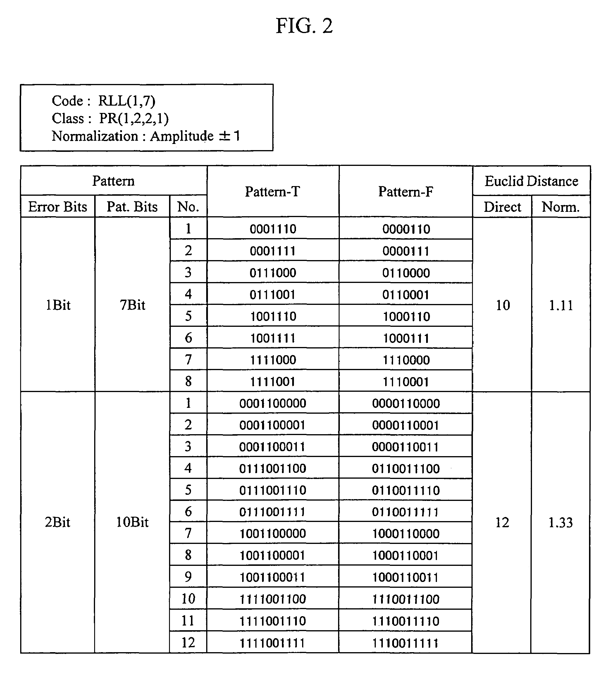
[0147]FIG. 12 shows a summary of the Euclidean distance and the edge shift direction for 1-bit error patterns for the PR(1,2,1) and PR(a,b,c) classes adapted to the RLL(1,7) code. As shown in the drawing, there are two combinations of patterns for the 1-bit error, and the Euclidean distance for a fixed target level is 6. The definition of the edge shift direction for each pattern is as shown.

[0148]First, the calculation of S-SEAT will be described.

[0149]FIG. 13 shows a summary of the target signal levels for a ...

embodiment 2

Circuit Configuration

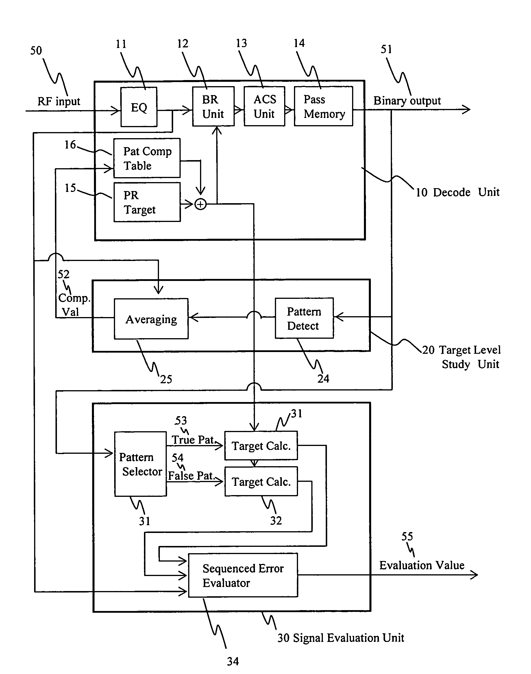
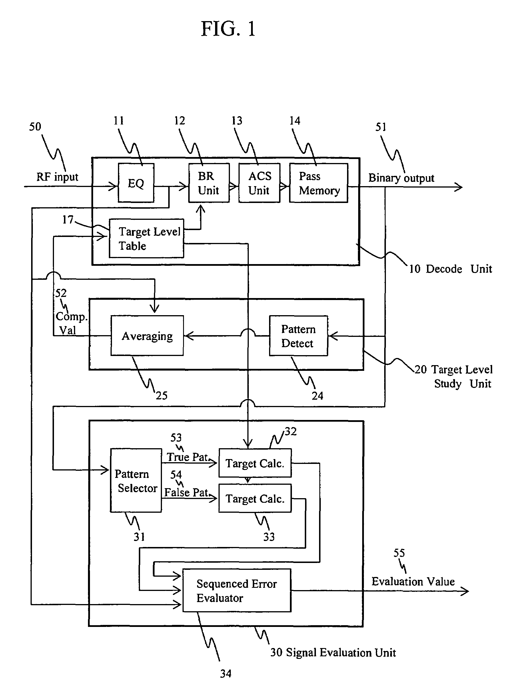
[0191]Hereafter, the configuration of an example of a circuit suitable for the calculation of S-SEAT and V-SEAT is described with reference to the drawings.

[0192]FIG. 1 shows the configuration of an S-SEAT calculation circuit mounted on an optical disc apparatus of the invention. The circuit consists of a decoding unit 10, a target level studying unit 20, and a signal evaluation unit 30.

[0193]Initially, the decoding unit 10 is described. The decoding unit 10 includes a waveform equalizer 11, a branch metric calculation unit 12, an ACS (Add Select Compare) unit 13, a path memory 14, and a target level table 17. A read signal 50, which is converted into a digital value in advance by an AD converter, is equalized by an FIR filter in the waveform equalizer 11. The read signal 50 is then fed to the branch metric calculation unit 12, where the square of the error from a target value (“branch metric value”) is calculated for each bit sequence. For the target value for ...

embodiment 3

Cases where Branch Metric Calculation is Carried out using Absolute Values

[0244]As mentioned above, in a Viterbi decoder, in order to obtain a most feasible binarization result, a branch metric value is used that is obtained by adding up the square of the difference between read signal and target signal. Such a Viterbi decoder will be hereafter referred to as the squared system. The squared value Δ2 of the difference between read signal and target level is as follows:

[0245]Δ2=(Vsignal⁡[t]-Vtarget⁡[n])2=(Vsignal⁡[t])2-2⁢Vsignal⁡[t]⁢Vtarget⁡[n]+(Vtarget⁡[n])2(Eq.⁢A⁢-⁢1)

where Vsignal[t] is the level of read signal at time t, and Vtarget[n] is a target signal level corresponding to a bit sequence n. In the Viterbi decoder, binarization is carried out such that the Δ2 accumulated value becomes minimum. The first term on the right hand side indicates the level of read signal, which is common to all bit sequences and therefore does not need to be calculated. In the case of a Viterbi decode...


PUM

PropertyMeasurementUnit
write poweraaaaaaaaaa
wavelengthaaaaaaaaaa

Abstract

A method of evaluating the quality of a read signal from the viewpoint of the detection margin of a Viterbi decoder in the PRML method in which a target signal level varies depending on the read signal, and an optical disc apparatus implementing the method. A method of evaluating the quality of a signal pattern comprising a combination of minimum run lengths from the viewpoint of edge shift, and an optical disc apparatus implementing the method. From the target signal level that varies depending on the read signal, a target signal is generated based on a decoding result, and an error target signal is generated in which the decoding result is edge-shifted. The signal quality is evaluated by calculating a Euclidean distance between these signals and the read signal. A virtual state that is not included in the Viterbi decoder and that is less than the minimum run length is defined, and a target signal level for the virtual state is generated using a target signal level table inside the Viterbi decoder, based on the concept of convolution. In this way, the signal quality can be evaluated by the same method as mentioned above even in cases where the pattern of a combination of the minimum run lengths has edge-shifted.

Description

CLAIM OF PRIORITY[0001]The present application claims priority from Japanese application JP 2004-138530 filed on May 7, 2004 and Japanese application JP 2004-377369 filed on Dec. 27, 2004, the contents of which are hereby incorporated by reference into this application.CROSS REFERENCE TO RELATED APPLICATION[0002]U.S. patent applications Ser. No. 10 / 643,975 and No.10 / 774,587 are co-pending applications of this application. The contents of which are incorporated herein by cross-reference.BACKGROUND OF THE INVENTION[0003]1. Field of the Invention[0004]The present invention relates to an optical disc apparatus for recording information by forming on a recording medium a recording mark with a different physical property from that of other parts of the medium.[0005]2. Description of Related Art[0006]With increases in the speed and density of optical discs, the PRML (Partial Response Maximum Likelihood) read signal processing method is becoming more and more indispensable. As an example of...

Claims


Application Information

Patent Timeline
Patent Type & Authority Patents(United States)
IPC IPC(8): H04L27/06G11B20/10G11B7/0045G11B7/005G11B7/125G11B20/18
CPCG11B20/10009G11B20/10083G11B20/10092G11B20/10101G11B20/10111G11B20/1012G11B20/10129G11B20/10166G11B20/10296G11B7/005G11B2020/1288G11B2220/2541G11B20/10G11B20/18
Inventor MINEMURA, HIROYUKI
Owner HITACHI-LG DATA STORAGE
Why Eureka
Try Eureka