Control system for internal combustion engine

a control system and internal combustion engine technology, applied in the direction of electric control, ignition automatic control, instruments, etc., can solve the problems of degraded drivability, reduce the accuracy of air-fuel ratio control, etc., and achieve the effect of improving the accuracy of ignition timing control

Inactive Publication Date: 2008-10-21
HONDA MOTOR CO LTD
View PDF22 Cites 8 Cited by
  • Summary
  • Abstract
  • Description
  • Claims
  • Application Information

AI Technical Summary

Benefits of technology

[0013]With the configuration of this control system, an air-fuel ratio control parameter for controlling the air-fuel ratio of a mixture such that it becomes equal to a target air-fuel ratio is calculated according to an air-fuel ratio parameter indicative of the air-fuel ratio of exhaust gases flowing through an exhaust passage of the engine; an operating condition parameter indicative of an operating condition of a variable intake mechanism is corrected according to one of the air-fuel ratio control parameter and the air-fuel ratio parameter; and the amount of fuel to be supplied to a combustion chamber is determined according to the corrected operating condition parameter and the air-fuel ratio control parameter. In this case, the amount of intake air drawn into a cylinder of the engine is changed as desired by the variable intake mechanism, and hence the operating condition parameter indicative of the operating condition of the variable intake mechanism corresponds to a value indicative of the amount of the intake air drawn into the cylinder. Therefore, during execution of air-fuel ratio control, when a detection value of the operating condition parameter deviates from an actual value, an actual air-fuel ratio of the mixture deviates toward a leaner side or a richer side with respect to the target air-fuel ratio due to the deviation of the detection value. On the other hand, the air-fuel ratio control parameter is calculated as a value for controlling the air-fuel ratio of the mixture such that it becomes equal to the target air-fuel ratio, according to the air-fuel ratio parameter, in other words, a value indicative which of the leaner side and the richer side the air-fuel ratio is controlled to, so that the air-fuel ratio control parameter reflects the above-described deviation of the air-fuel ratio. Further, the air-fuel ratio parameter is a value indicative of the air-fuel ratio of exhaust gases flowing through the exhaust passage of the engine, and hence when the air-fuel ratio of the mixture is controlled such that it becomes equal to the target air-fuel ratio, the air-fuel ratio parameter as well is detected as a value reflecting the above-described deviation of the air-fuel ratio. Therefore, by correcting the operating condition parameter according to the air-fuel ratio control parameter or the air-fuel ratio parameter, thus calculated or detected, it is possible to properly correct the deviation between the detection value of the operating condition parameter and the actual value. As a result, even when the detection value of the operating condition parameter deviates from the actual value due to a drift of the detection value detected by the operating condition parameter-detecting means, and wear, contamination, play caused by aging, etc., occurring in component parts of the variable intake mechanism, it is possible to properly determine the fuel amount while compensating for the influence of the above deviation. This makes it possible to properly carry out the air-fuel ratio control, thereby making it possible to ensure a stable combustion state and excellent reduction of exhaust emissions.
[0025]With the configuration of this preferred embodiment, the ignition timing is determined according to the corrected operating condition parameter when the load parameter is within a first predetermined range, whereas when the load parameter is within a second predetermined range different from the first predetermined range, the ignition timing is determined according to the detected flow rate of air. In this case, the corrected operating condition parameter and the detection value of the flow rate of air are both indicative of the amount of intake air. Therefore, by setting the first predetermined range to a range where the corrected operating condition parameter becomes higher in reliability than the detection value of the flow rate of air, and setting the second predetermined range to a range where the detection value of the flow rate of air becomes higher in reliability than the corrected operating condition parameter, it is possible, in both of the load regions, to determine the ignition timing according to a value indicative of the amount of intake air, higher in reliability, whereby it is possible to further enhance the accuracy of the ignition timing control.

Problems solved by technology

As a result, when the operating condition parameter is corrected using the thus changed control state value, a value obtained by correcting the operating condition parameter is also changed in an oscillating manner to reduce the accuracy of the air-fuel ratio control.
This can cause occurrence of surging and fluctuation in the rotational speed of the engine, resulting in the degraded drivability.

Method used


Image

  • Control system for internal combustion engine
  • Control system for internal combustion engine
  • Control system for internal combustion engine

Examples


first embodiment

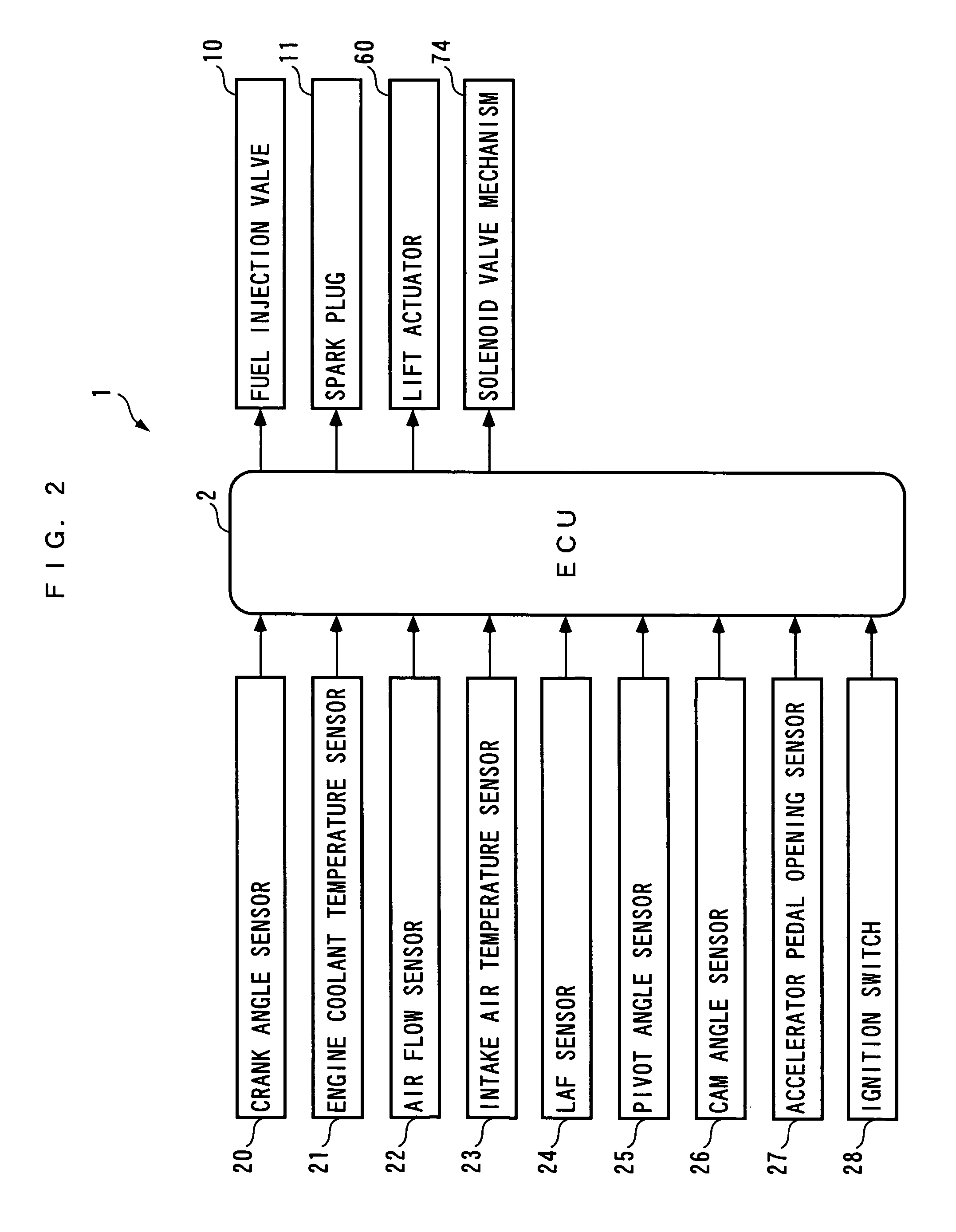
[0067]Hereafter, a control system for an internal combustion engine, according the present invention will be described with reference to the drawings. The control system 1 includes an ECU 2, as shown in FIG. 2. As described hereinafter, the ECU 2 carries out control processes, including an air-fuel ratio control process and an ignition timing control process, depending on operating conditions of the internal combustion engine (hereinafter simply referred to as “the engine”) 3.

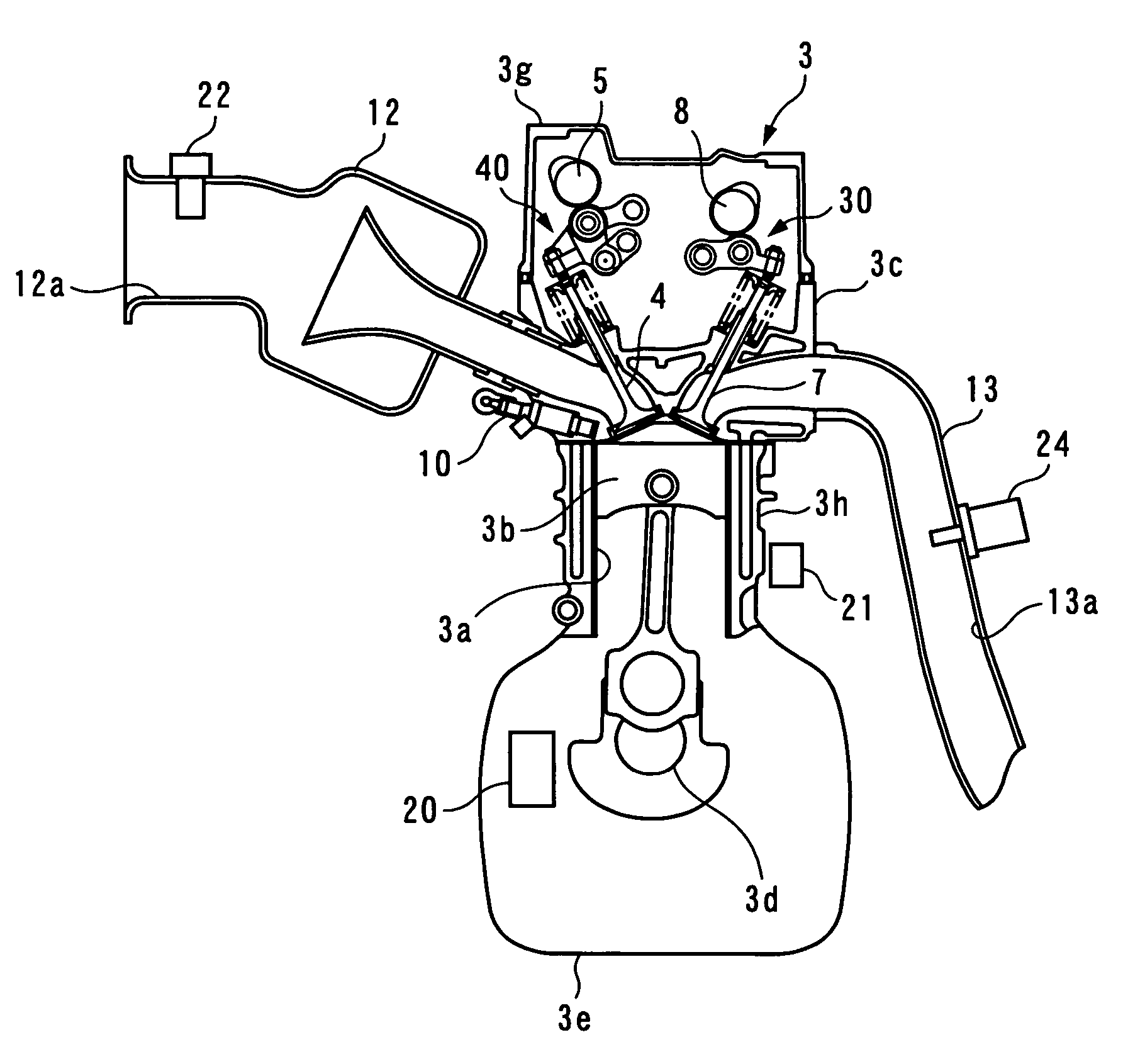
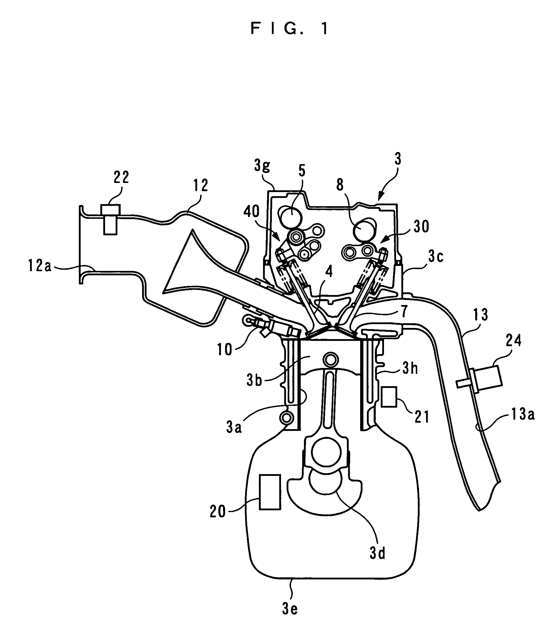
[0068]Referring to FIGS. 1 and 3, the engine 3 is an in-line four-cylinder gasoline engine having a four pairs of cylinders 3a and pistons 3b (only one pair of which is shown), and installed on a vehicle, not shown, provided with an automatic transmission. The engine 3 includes an intake valve 4 and an exhaust valve 7 provided for each cylinder 3a, for opening and closing an intake port and an exhaust port thereof, respectively, an intake camshaft 5 and intake cams 6 for actuating the intake valves 4, a variabl...

second embodiment

[0334]Next, a description will be given of the results of control by the control system 1A configured as above. FIG. 41 shows an example of the results of execution of feedback control of the air-fuel ratio using the air-fuel ratio correction coefficient KSTR and a corrected value-calculating process, during idling of the engine 3, when the valve lift Liftin calculated based on the signal output from the pivot angle sensor 25 (the calculated values are indicated by a solid line) deviates toward the smaller side than an actual valve lift (values of which are indicated by a two-dot chain line).

[0335]In FIG. 41, regions where the lift correction value Dliftin_comp and the corrected valve lift Liftin_comp are both updated are indicated by hatching. Further, as described hereinabove, since during idling of the engine 3, the cam phase Cain is controlled to the range where Cain_ret≦Cain≦Cain_adv holds, neither the corrected cam phase Cain_comp nor the phase correction value Dcain_comp is ...


PUM


Abstract

A control system for an internal combustion engine, which is capable of properly performing air-fuel ratio control and ignition timing control according to an actual amount of intake air, even when reliability of the results of detection of the operating condition of a variable intake mechanism is low. The control system for controlling air-fuel ratio and ignition timing includes an ECU. The ECU calculates a target air-fuel ratio, calculates an air-fuel ratio correction coefficient, calculates a statistically processed value of an air-fuel ratio index value, calculates a corrected valve lift and a corrected cam phase, and determines a fuel injection amount according to the corrected valve lift, the corrected cam phase, and the air-fuel ratio correction coefficient.

Description

CROSS-REFERENCE TO RELATED APPLICATION[0001]This application is a National Stage entry of International Application No. PCT / JP2005 / 010692, filed Jun. 10, 2005, the entire specification claims and drawings of which are incorporated herewith by reference.FIELD OF THE INVENTION[0002]The present invention relates to a control system for an internal combustion engine, which controls the amount of intake air drawn into cylinders of the engine via a variable intake mechanism and controls an air-fuel ratio and ignition timing.BACKGROUND ART[0003]Conventionally, a control system for an internal combustion engine, which controls the amount of intake air drawn into cylinders of the engine via a variable intake mechanism, has been proposed in Patent Literature 1. This control system is comprised of an air flow sensor that detects the flow rate of air flowing through an intake passage of the engine, a crank angle sensor that detects a state of rotation of a crankshaft, an accelerator pedal openi...

Claims


Application Information

Patent Timeline
Patent Type & Authority Patents(United States)
IPC IPC(8): G06G7/70F02D41/04F02M25/07F01L1/34F01L13/00F02D13/02F02D37/02F02D41/14F02D41/22F02D43/00F02D45/00F02P5/04F02P5/15
CPCF01L1/34F01L1/3442F01L13/0021F01L13/0063F02D37/02F02D41/1401F02D41/1454F02D41/221F01L2001/3443F02D41/187F02D2041/001
Inventor YASUI, YUJISATO, MASAHIROSAITO, MITSUNOBUTAGAMI, HIROSHIHIGASHITANI, KOSUKE
Owner HONDA MOTOR CO LTD
Why Eureka
Try Eureka