
Ammonia gas sensor method and device

a technology of ammonia gas and ammonia gas, which is applied in the direction of instruments, material heat development, material electrochemical variables, etc., can solve the problems of inability to properly function of current and used ammonia sensors, long lag time, and inability to use high temperature techniques. to achieve the effect of accurate determination of the total nh3 concentration

Inactive Publication Date: 2008-10-28
EMISENSE TECH
View PDF27 Cites 10 Cited by
  • Summary
  • Abstract
  • Description
  • Claims
  • Application Information

AI Technical Summary

Benefits of technology

"The present invention is about a new method and design for measuring ammonia gases in exhaust streams, such as from automobiles and power plants, to detect residue of gaseous ammonia or urea added to mitigate NOx emissions. The sensor is designed for high-temperature use and can measure total NH3 concentration in an exhaust gas stream. The sensor may also include a NOx and oxygen sensor to accurately determine the total NH3 concentration based on the oxygen and NOx concentration. The technical effects of this invention include improved accuracy in measuring ammonia concentration in exhaust streams and the ability to detect residue of ammonia or urea."

Problems solved by technology

A review of pertinent patent and other literature revealed that currently known and used ammonia sensors are incapable of proper function at temperatures higher than 500° C. while providing a detection limit of 1 ppm.
These techniques inherently preclude use at high temperatures, since polymers are not stable chemically at such temperatures.
For optical systems, however, the gas inputs must be transferred to an analysis chamber, resulting in long lag times. Further, the associated equipment for such optical sensors is generally bulky and highly expensive.
The primary problem with semi-conductor oxides in general is that they measure bulk properties based on adsorption of gases, and there is a significant issue of cross-contamination as all gases tend to adsorb on high-surface area ceramic substrates to some extent, resulting in significant errors in measurement.
The main problem for ammonia measurements in engine exhaust streams is cross-contamination with carbon monoxide (CO), and oxides of nitrogen (NOx).
This results in the requirement for a very complex electronics package to calculate out the NH3 concentration, which is undesirable and cost ineffective.
Another problem faced in semiconductor sensors is that they have a low maximum temperature for use.
Further, it has been observed that in many circumstances, semiconductor sensors typically have a long response time to fluctuations in ammonia concentration since they are kinetically limited by gas adsorption.
This approach has two challenges: (1) the limited temperature capability of semiconductor based sensors (generally less than 450° C.) and (2) the complexity of accompanying electronics required to extract out meaningful gas concentrations from the signals of various sensing elements.
Type II and Type III sensors are clearly unsuitable for high-temperature applications due to the nature of the materials used, generally nitrates, which are unstable and sometimes explosive at high temperatures.
Type I sensors for NH3 sensing are feasible, but impractical.
Due to the presence of oxygen in the exhaust stream, which would interfere with the measurement, elaborate pumping cells are required for removing the oxygen prior to gas sensing.
This makes the device complex and increases operating costs to the point where it is not an attractive option.
The same problem of initial oxygen removal exists for amperometric devices for gas sensing.

Method used


Image

  • Ammonia gas sensor method and device
  • Ammonia gas sensor method and device
  • Ammonia gas sensor method and device

Examples


example 1

[0035]An experiment was set up to test the concept of using a catalyst at two different temperatures so that when the gas passes through the high temperature catalyst all of the NH3 is converted to NO and when the gas passes through the low temperature catalyst the NH3 is converted to N2 and H2O. A catalyst was fabricated by chopping up some high purity Al2O3 insulation felt into small chips approximately 1 mm×1 mm×1 mm. The felt chips were then impregnated with a RuCl2 solution followed by drying at 80° C. for 1 hour. The dried impregnated chips were then installed into a test apparatus that was a ⅜″ outside diameter stainless steel tube with compression fittings attached to each end of the tube. The felt chips were held in place with a piece of nickel mesh on each side of the bed of chips to keep them properly located within the stainless steel tube and prevent them from being displaced by the flowing gas. The tube apparatus was then installed in a small tubular resistively heated...

example 2

[0037]A second experiment was set up to test the concept of using a catalyst at two different temperatures so that when the gas passes through the high temperature catalyst all of the NH3 is converted to NO and when the gas passes through the low temperature catalyst the NH3 is converted to N2 and H2O. A catalyst was fabricated by mixing 10 wt. % La2O3 / Al2O3 followed by infiltration of Nickel nitrate to produce a 15 wt. % Ni composition. This precursor powder was then dried and calcined at about 800° C. in air. The calcined powder was then installed into a test apparatus that was a ⅜″ outside diameter stainless steel tube with compression fittings attached to each end of the tube. The packed powder was held in place with a piece of nickel mesh on each side of the bed of powder to keep it properly located within the stainless steel tube and to prevent the powder from being displaced by the flowing gas. The tube apparatus was then installed in a small tubular resistively heated furnac...


PUM

PropertyMeasurementUnit
temperaturesaaaaaaaaaa

Abstract

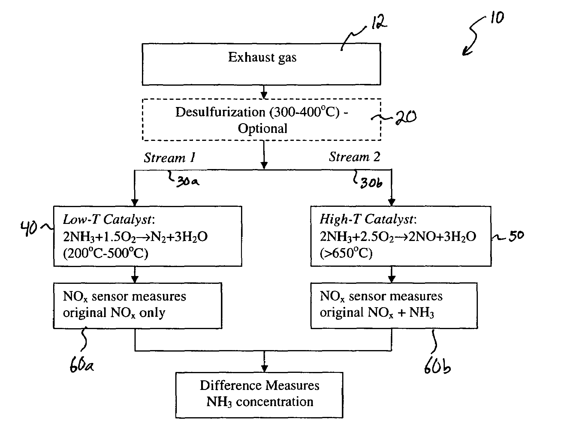
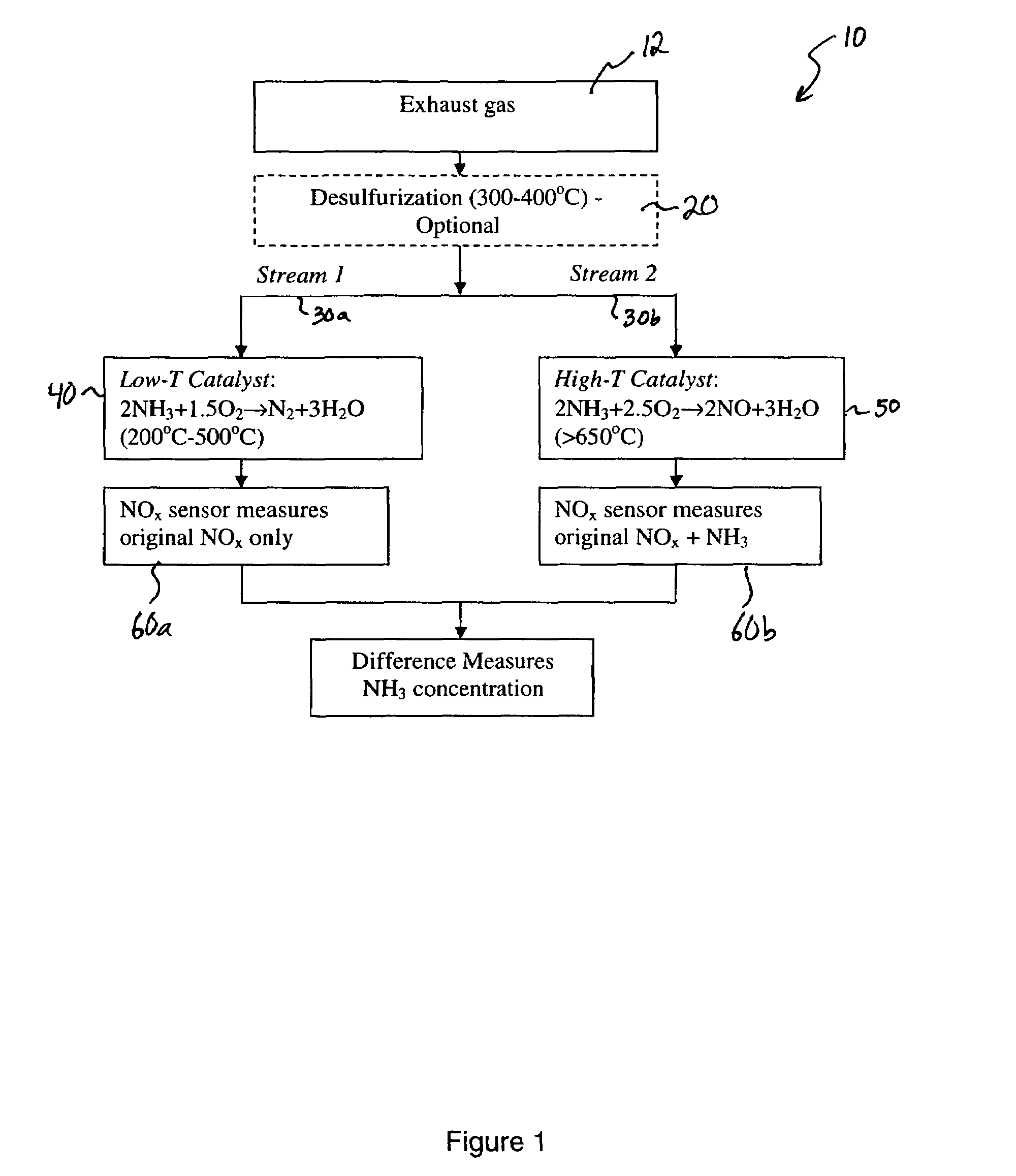
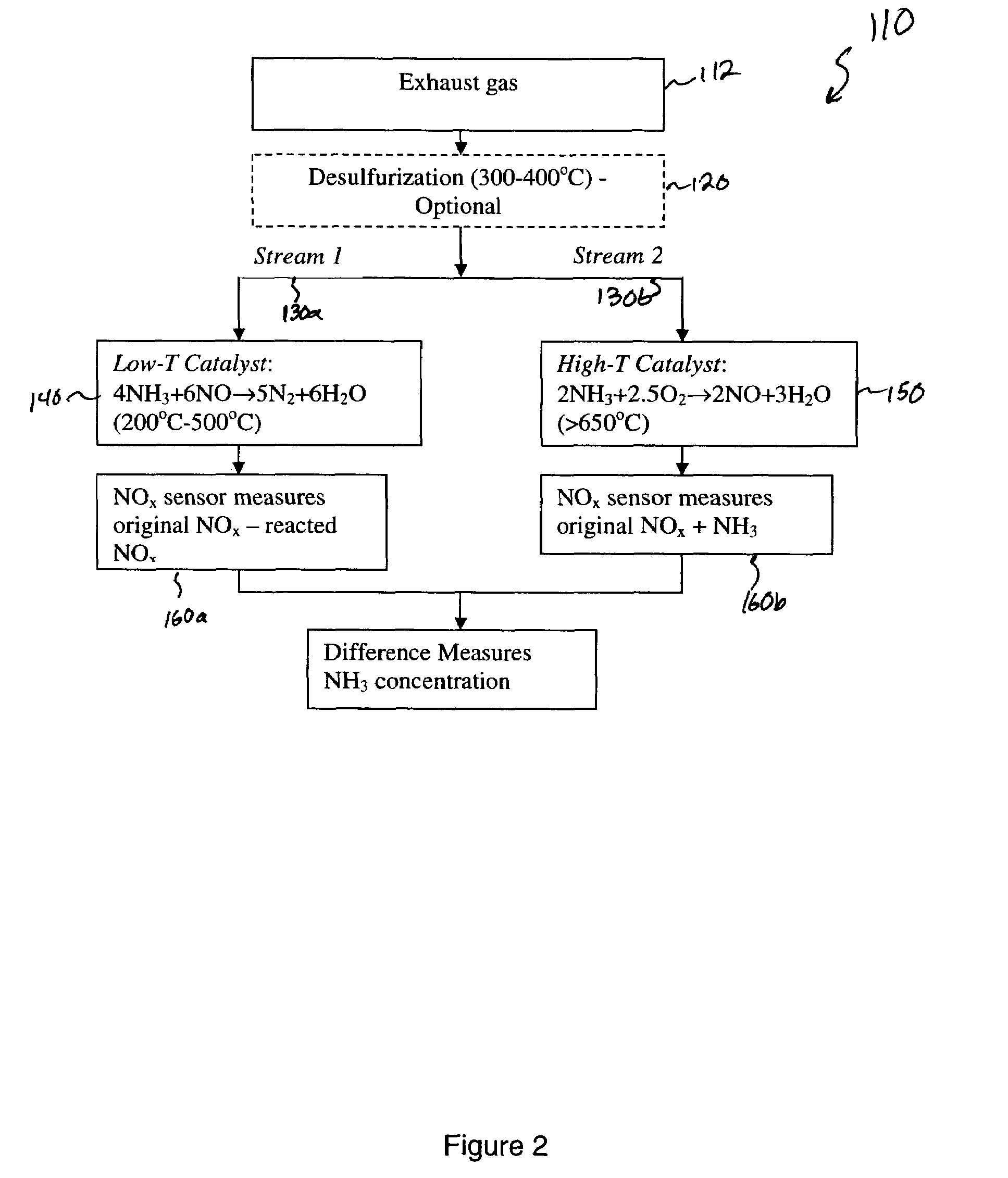
A mixed potential sensor device and methods for measuring total ammonia (NH3) concentration in a gas is provided. The gas is first partitioned into two streams directed into two sensing chambers. Each gas stream is conditioned by a specific catalyst system. In one chamber, in some instances at a temperature of at least about 600° C., the gas is treated such that almost all of the ammonia is converted to NOx, and a steady state equilibrium concentration of NO to NO2 is established. In the second chamber, the gas is treated with a catalyst at a lower temperature, preferably less than 450° C. such that most of the ammonia is converted to nitrogen (N2) and steam (H2O). Each gas is passed over a sensing electrode in a mixed potential sensor system that is sensitive to NOx. The difference in the readings of the two gas sensors can provide a measurement of total NH3 concentration in the exhaust gas. The catalyst system also functions to oxidize any unburned hydrocarbons such as CH4, CO, etc., in the gas, and to remove partial contaminants such as SO2.

Description

RELATED APPLICATIONS[0001]This application is related to and claims the benefit of U.S. Provisional Patent Application Ser. No.: 60 / 593,250, of Balakrishnan Nair and Jesse Nachlas filed on Dec. 28, 2004, and entitled “Ammonia Gas Sensor Method and Device.” This application is incorporated herein by this reference in its entirety.FIELD OF THE INVENTION[0002]The present invention relates in general to the measurement of ammonia gases in gases or gas streams. In some embodiments, the invention relates to ammonia measurement in streams from both mobile sources such as automobiles and trucks and stationary sources such as power plants, the residue of gaseous ammonia or urea that is originally added to mitigate NOx emissions in processes such as selective catalytic reduction.BACKGROUND OF THE INVENTION[0003]There is a need in the art for ammonia sensors that can detect and measure NH3 at temperatures higher than 500° C. for emissions control systems. Typically, for control applications, t...

Claims


Application Information

Patent Timeline
Patent Type & Authority Patents(United States)
IPC IPC(8): G01N33/00G01N1/22G01N27/04G01N27/27
CPCG01N33/0054Y10T436/175383Y10T436/25875Y10T436/177692Y10T436/25125Y10T436/17Y10T436/179228Y02A50/20
Inventor NAIR, BALAKRISHNAN G.NACHLAS, JESSE
Owner EMISENSE TECH
Learn More