
Opto-semiconductor devices

a technology of optosemiconductor and semiconductor chip, which is applied in the direction of laser optical resonator construction, lasers, semiconductor lasers, etc., can solve the problems of difficult scrubbing methods, affecting the polarization characteristic and affecting the polarization of the optosemiconductor devi

Active Publication Date: 2008-10-28
USHIO OPTO SEMICON
View PDF2 Cites 7 Cited by
  • Summary
  • Abstract
  • Description
  • Claims
  • Application Information

AI Technical Summary

Benefits of technology

The uniform reaction layer and reduced stress on the optical waveguide result in improved polarization characteristics of the semiconductor laser device, minimizing variations in the polarization angle of the emitted laser light.

Problems solved by technology

Since the semiconductor chip is scrubbed on the support plate or the like, however, the bonding material under the semiconductor chip is liable to be forced out and swell around the semiconductor chip.
Therefore, the laser light emitted from the emitting facet (facet) of the semiconductor laser chip impinges on the swollen portion of the bonding material and cannot be emitted further.
In fixing the semiconductor laser chip junction down, therefore, the scrubbing method is difficult to employ.

Method used


Image

  • Opto-semiconductor devices
  • Opto-semiconductor devices
  • Opto-semiconductor devices

Examples


first embodiment

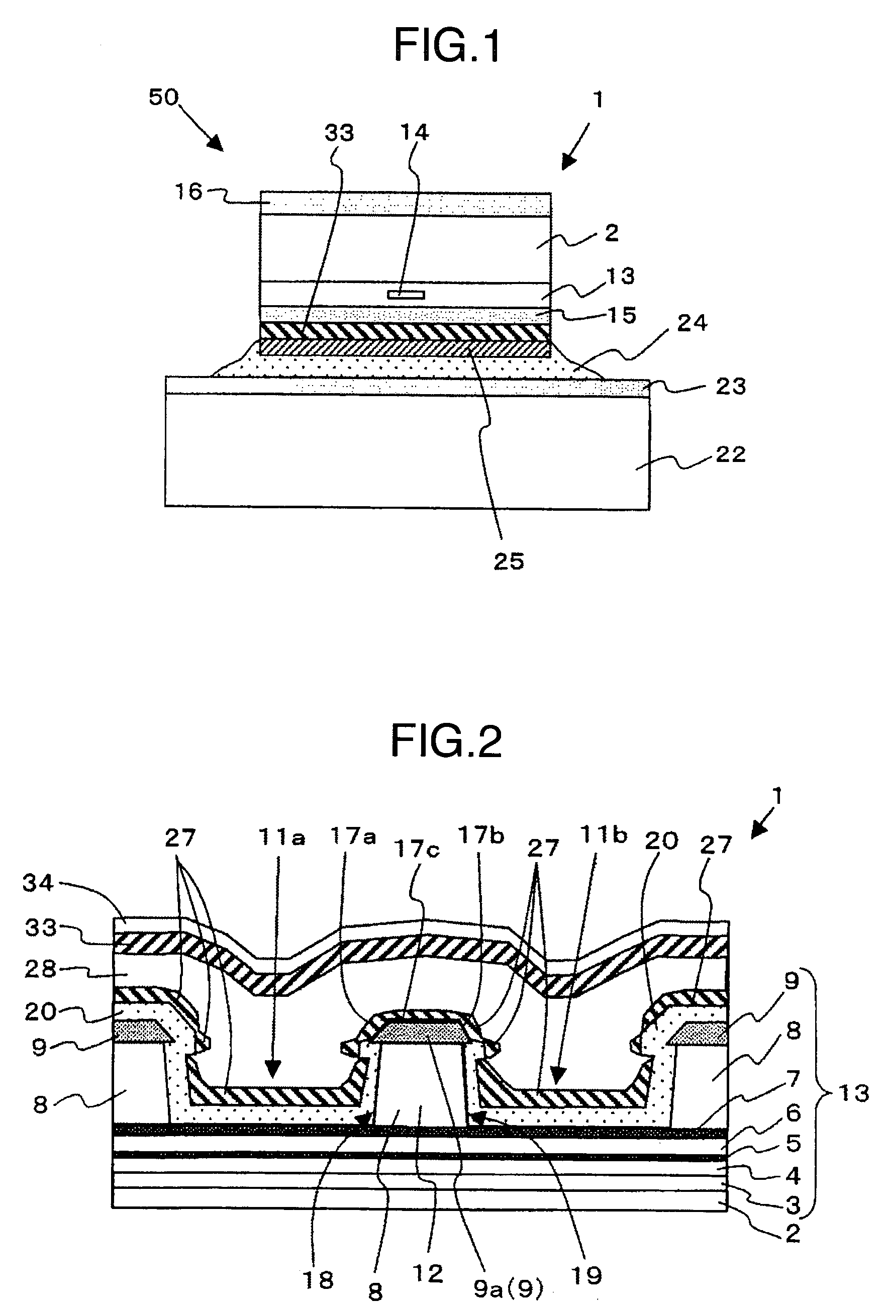
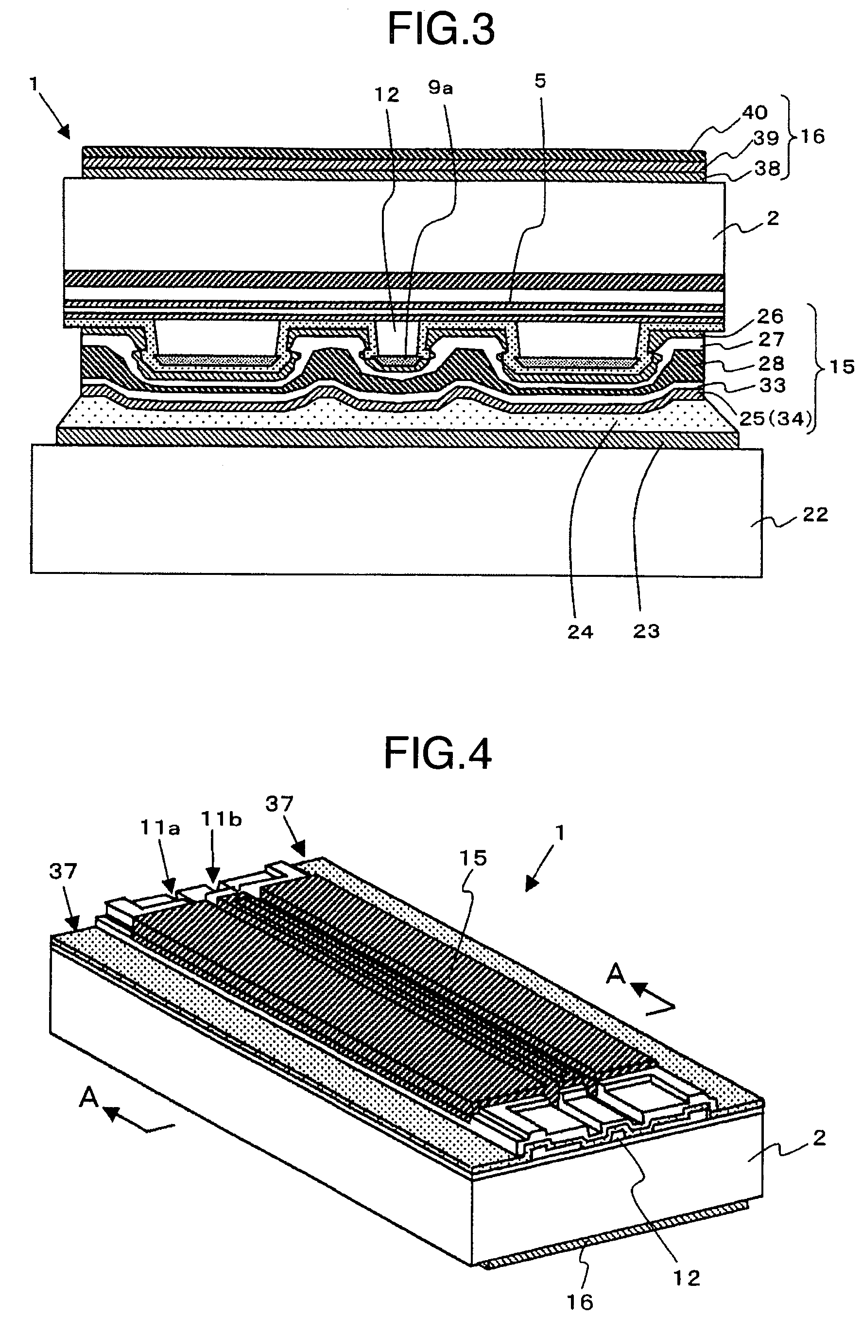
[0051]FIGS. 1 to 12 are diagrams showing an opto-semiconductor device (semiconductor laser device) according to a first embodiment of the invention. The first embodiment represents an application of the invention to the fabrication of a red semiconductor laser in the band on the order of 0.6 μm. The first embodiment also represents an example of the opto-semiconductor device (semiconductor laser device) having built therein a semiconductor laser element of p type (P type) as a second conduction type in the wavelength band on the order of 650 nm. This semiconductor laser element has a structure in which multiple semiconductor layers of AlGaInP, GaInP, GaAs, etc. are formed on a GaAs substrate.

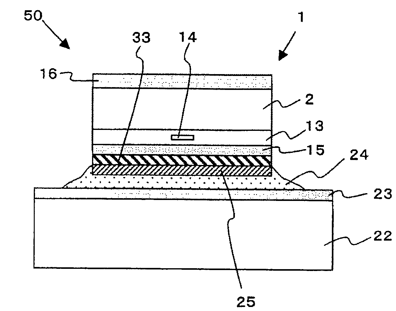
[0052]Before explaining a specific opto-semiconductor device according to the first embodiment, the features of the invention are explained with reference to the schematic diagram of FIG. 1. FIG. 1 is a diagram corresponding to FIG. 18. FIG. 1 shows the opto-semiconductor element (semiconductor ...

second embodiment

[0110]FIGS. 15 to 17 are diagrams showing an opto-semiconductor device according to a second embodiment of the invention. FIG. 15 is a schematic diagram showing a part of the opto-semiconductor device, FIG. 16 a perspective view of the semiconductor laser element built in the opto-semiconductor device, and FIG. 17 a sectional view of the semiconductor laser element cut away along the plane perpendicular to the resonator.

[0111]In the semiconductor laser element 100 according to this embodiment, a n-type buffer layer 102 of GaAs, a n-type clad layer (first clad layer) 103 of AlGaInP, an active layer 104 of a multi-quantum well structure having a barrier layer of AlGaInP and a well layer of GaInP, a p-type clad layer (first second clad layer) 105 of AlGaInP and a p-type etch stop layer 106 of AlGaInP are stacked on the first surface of a n-type GaAs substrate (semiconductor substrate) 101. A p-type clad layer (third second clad layer) 107 of AlGaInP is formed in stripe on the central p...


PUM


Abstract

An opto-semiconductor device. An opto-semiconductor element includes a semiconductor substrate, a multilayered semiconductor layer formed on a first surface of the semiconductor substrate and having a resonator, a first electrode with multiple conductive layers formed on the multilayered semiconductor layer, and a second electrode formed on a second surface of the semiconductor substrate. A support substrate has a first surface formed with a fixing portion having a conductive layer for fixing the first electrode connected thereto through a bonding material. Bonding material and conductive layers forming the first electrode react to form a reaction layer. The difference in thermal expansion coefficient between semiconductor substrate and support substrate is not more than ±50%. A second barrier metal layer not reactive with bonding material is formed inside the first electrode uppermost conductive layer, while uppermost layer reacts with the bonding material to form the reaction layer.

Description

INCORPORATION BY REFERENCE[0001]The present application claims priority from Japanese application JP2005-095375 filed on Mar. 29, 2005, the content of which is hereby incorporated by reference into this application.BACKGROUND OF THE INVENTION[0002]This invention relates to opto-semiconductor devices or in particular to a technique effectively applicable to the fabrication of a laser diode (LD) of a ridge structure.[0003]A semiconductor laser (LD) as an opto-semiconductor element is widely used as a light source of an optical communication system or an information processing system. A visible light semiconductor laser is used as a light source of an information processing system such as a document file system as well as CD, DVD device, laser printer, POS and bar code reader.[0004]The semiconductor laser element (opto-semiconductor element) has such a structure that a multiplicity of semiconductor layers (multiple growth layers) are formed by epitaxial growth on a first surface of a s...

Claims


Application Information

Patent Timeline
Patent Type & Authority Patents(United States)
IPC IPC(8): H01S3/097
CPCB82Y20/00H01S5/0224H01S5/02272H01S5/22H01S5/02212H01S5/02476H01S5/0425H01S5/16H01S5/2081H01S5/34326H01S2301/14H01S2301/176H01S5/04252H01S5/04254H01S5/0234H01S5/0237
Inventor INOUE, YUTAKASAITOH, KAZUNORIHAMADA, HIROSHIHAGIMOTO, MASATOSORIMACHI, SUSUMU
Owner USHIO OPTO SEMICON
Learn More