Fuel vapor storage and recovery apparatus with heat exchanger

a technology of heat exchanger and fuel vapour, which is applied in the direction of mechanical equipment, combustion air/fuel air treatment, machines/engines, etc., can solve the problems of presenting bad adsorption performance, and achieve the effect of reducing the temperature of parts

Inactive Publication Date: 2008-11-04
INERGY AUTOMOTIVE SYST RES (SA)
View PDF24 Cites 28 Cited by
  • Summary
  • Abstract
  • Description
  • Claims
  • Application Information

AI Technical Summary

Benefits of technology

[0011]The present invention is based on the idea that the heat shield can advantageously be used to locate an air heater, i.e. a heat exchanger in its proximity to use the captured heat and even, to help reducing the temperature of the part of the fuel tank close to the exhaust pipe. The heat emitted from the heat source to the heat shield (or the temperature of the heat shield) suffices to heat air guided through the heat exchanger. The heat exchanger may be located above the heat shield (close to the tank), integrated to surface of the heat shield or even be located below the heat shield (close to the exhaust pipe) since its surface usually still has a temperature of up to about 150° C. and thus, between the heat shield and the fuel tank, the air may be heated to a temperature of about 100° C. or above, depending on the individual design of the fuel vapour storage and recovery apparatus. Furthermore, the heat exchanger assists the heat shield in blocking heat which is emitted from the exhaust pipe and absorbed by the fuel tank.
[0018]According to the invention, the fuel tank is a hollow body made of a material which does not withstand high temperatures (typically above 80° C.) for a long time without being thermally insulated. The invention gives good results with fuel tanks made of polymeric material. The polymeric material is preferably selected from the group consisting of polyethylene, polyethylene terephthalate, polybutylene terephthalate, polyamide, polyoxymethylene, polypropylene, elastomers and mixtures of two or more thereof. Preferably, the polymeric material comprises high density polyethylene (HDPE). In a specific embodiment, the hollow element also comprises a layer of barrier material like EVOH (at least partially hydrolysed ethylene—vinyl acetate copolymers). Alternatively, the HDPE may be surface treated (by fluorination, sulphonation or the like) in order to reduce its permeability to fuel.
[0031]Generally, such systems also include a vent port. It is namely so that when the fuel vapour / air mixture coming from the fuel tank passes through the canister, it is separated, i.e. only the fuel vapour is absorbed on the absorbent while the air is not. Since this air is clean, it can be sent back to the atmosphere, which is done through the vent port. Therefore, the conduit system may also includes a second control valve that either communicates the vapour storage canister with the exterior of the system (atmosphere) through a vent port or communicates the vapour storage canister with the heat exchanger through the second conduit means (b), said control valve also being operated by the ECM. Such a valve is not necessarily required since the system will work even if the canister communicates all the time with the second conduit means (b). However, the presence of such a valve avoids pressure drops in the second and third conduit means (b and c) when there is no purge taking place.

Problems solved by technology

Such a system has the drawback of presenting bad adsorption performances when the engine is running, because it is permanently heated then and that fuel vapours rather tend to desorb when temperature rises (see above).

Method used


Image

  • Fuel vapor storage and recovery apparatus with heat exchanger
  • Fuel vapor storage and recovery apparatus with heat exchanger
  • Fuel vapor storage and recovery apparatus with heat exchanger

Examples


Embodiment Construction

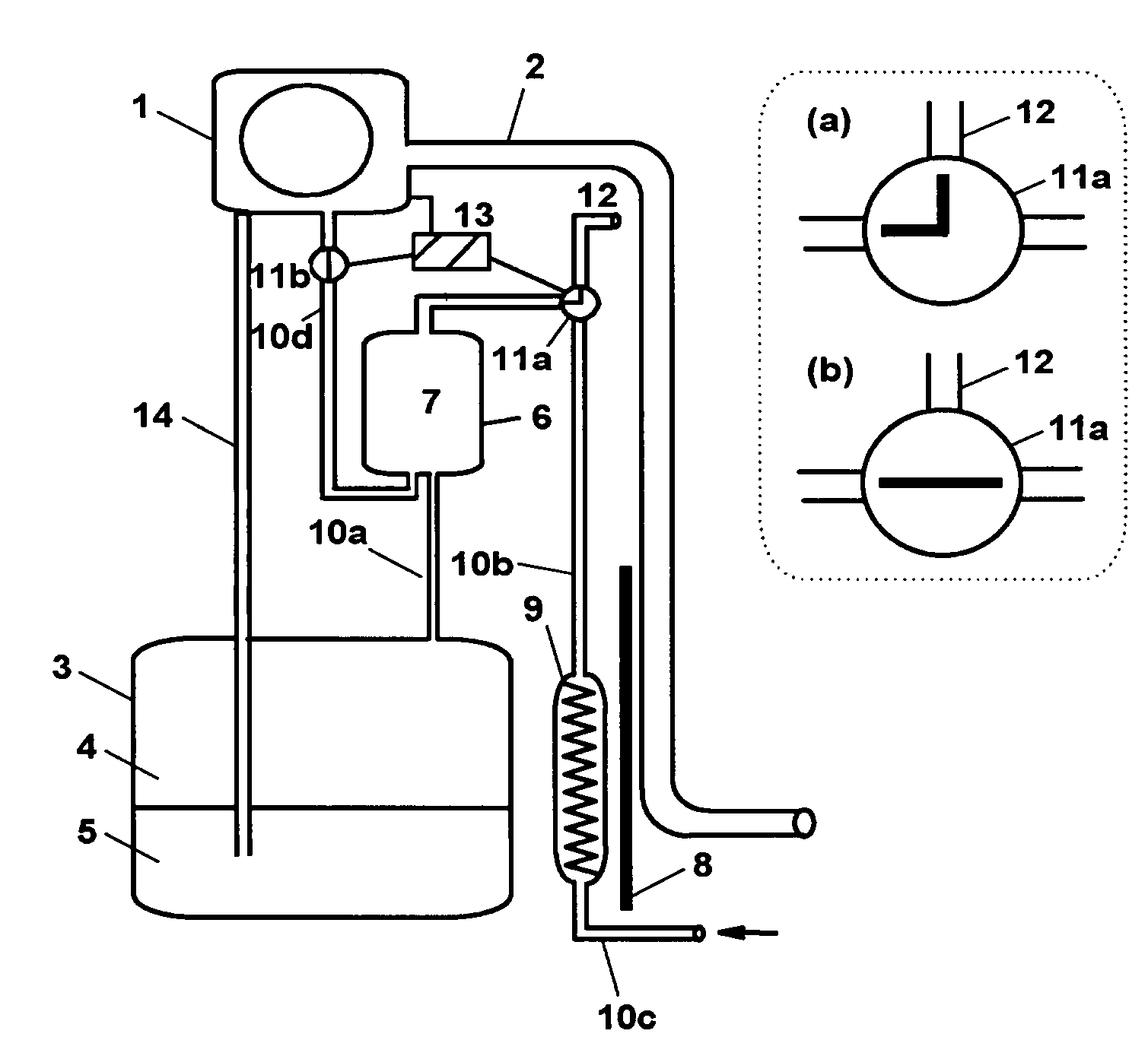
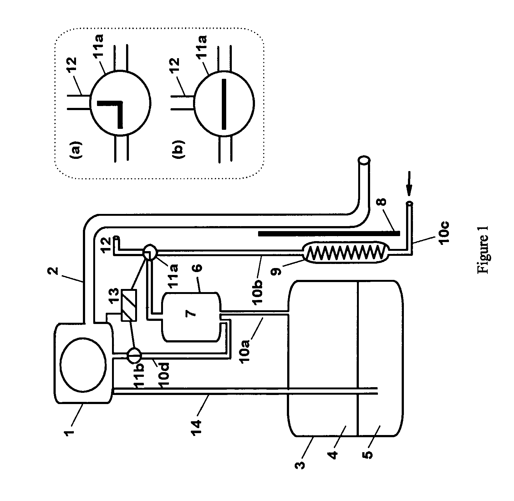
[0034]FIG. 1 shows a schematic view of a preferred embodiment of the evaporative emission control system of the invention. A motor vehicle, not shown, includes a fuel tank (3) having a variable volume of liquid fuel (5) therein, e.g. gasoline and / or methanol and a variable volume of fuel vapour / air mixture (4) above the liquid fuel (5). Liquid fuel (5) is delivered from the fuel tank (3) to an internal combustion engine (1) or a fuel processor of a fuel cell through a fuel delivery pipe (14).

[0035]The system includes a vapour storage canister (6) having therein a body of fuel vapour adsorbent material (7) such as activated carbon granules. The vapour storage canister (6) communicates with the fuel tank (3) above the liquid fuel (5) therein through a vapour conduit (10a).

[0036]A first control valve (11a) communicates the vapour storage canister (6) either with the exterior of the system through an open vent port (12) (position a), or with a heat exchanger (9) through a vapour / purge c...


PUM


Abstract

A fuel vapor storage and recovery apparatus for a fuel system of a motor vehicle including an internal combustion engine with an exhaust pipe and a fuel tank containing a fuel vapor / air mixture above a liquid fuel, the exhaust pipe being close to the fuel tank. The apparatus includes a vapor storage canister including a fuel vapor adsorbent material therein, a thermal insulation mechanism for thermally insulating at least a portion of the fuel tank from the heat generated by the exhaust pipe, and a beat exchanger. The heat exchanger is configured to heat to a purge temperature air guided there through by absorbing heat from the thermal insulation mechanism.

Description

BACKGROUND OF THE INVENTION[0001]1. Field of the invention[0002]The invention relates to a fuel vapour storage and recovery apparatus for the fuel system of a motor vehicle comprising a vapour storage canister containing adsorbent material, which is intended to trap and store vapours from the vehicle's fuel tank, and to purge stored vapour and condensate during operation of the vehicle's engine.[0003]2. Discussion of the Background[0004]Fuel vapour escaping from the fuel system is a source of hydrocarbon emission from the automobile. In particular, gasoline vapours may escape from the external vents of the fuel tank, either while driving or while at rest. Within the past several years a number of attempts have been made to limit the escape of gasoline into the atmosphere.[0005]There have been proposed evaporative emission control systems that involve the use of charcoal-filled canisters which are connected, through vapour lines, to the fuel tanks such that gasoline vapours from the ...

Claims


Application Information

Patent Timeline
Patent Type & Authority Patents(United States)
IPC IPC(8): F02M33/02F02G5/00F02M25/08
CPCF02M25/08F02M2025/0881
Inventor POTIER, VINCENT
Owner INERGY AUTOMOTIVE SYST RES (SA)
Why Eureka
Try Eureka