Radio oscillating and radar systems

a radio signal and radar technology, applied in the direction of braking system, using reradiation, instruments, etc., can solve the problems of difficult to ensure the necessary output power of radio signal, high cost of oscillation, low energy efficiency, etc., to achieve efficient generation of sideband waves, low cost, and alleviation of filters

Active Publication Date: 2008-11-04
NGK INSULATORS LTD
View PDF28 Cites 26 Cited by
  • Summary
  • Abstract
  • Description
  • Claims
  • Application Information

AI Technical Summary

Benefits of technology

[0008]According to a radar system using s sub-carrier light source such as a mode locking laser system, many signals are observed at an interval according to optional longitudinal mode in the oscillation spectrum. A plurality of radio signals are inevitably oscillated other than the desired signal of beat frequency. The thus generated radio signals are reflected by an object. It is thus needed to provide a frequency filter on the reception side, and to narrowly specify the pass band filter to eliminate many of the unnecessary radio signals.
[0011]An object of the present invention is to alleviate the necessity of a reception filter of severe specification of pass band and a radio signal generating system and an amplifier of high performance and high reliability, in a radio signal radiation system for a radar system, and to provide a radio signal radiation system of improved practical use.
[0023]It is thus possible to change a filter to be set in the downstream of the receiver, required in Japanese Patent publication No. 2002-162465A, to a low cost filter not requiring severe band pass property. Further, only sideband waves are required and a filter can be alleviated. It becomes further possible to generate sideband waves efficiently for the radio signal. It is thus possible to radiate a radio signal having an output power larger than that of a sub-carrier light source, so that the necessity of a high performance optical amplifier or electric amplifier is alleviated even when the signal is divided into plural routes. As described above, the present invention is effective for cost reduction.

Problems solved by technology

Such oscillation required a high cost due to the above two reasons.
The efficiency is low in the terms of energy, and it is thus difficult to assure a necessary output power of radio signal, particularly when the light is divided into plural routes.

Method used


Image

  • Radio oscillating and radar systems
  • Radio oscillating and radar systems
  • Radio oscillating and radar systems

Examples


example 1

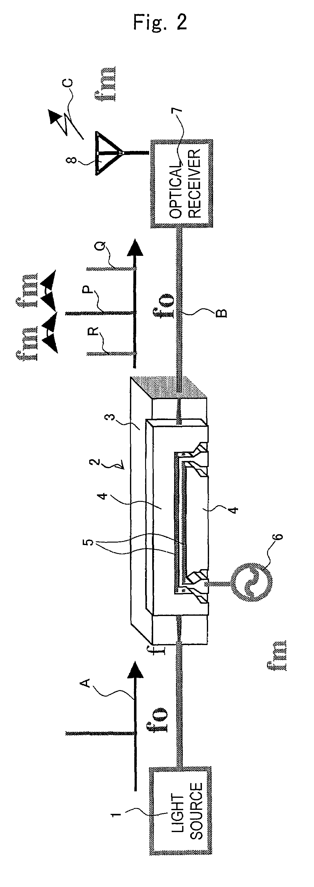
[0106]The radar system was produced using an optical modulator 2 shown in FIG. 13.

[0107]Specifically, Ti-diffusion waveguides 5A, 5B and CPW electrodes 4A, 4B and 4C were formed on a substrate of x-cut lithium niobate 3. As to the electrode structure, the gaps “G” between the central electrode 4B and ground electrodes 4A, 4C were 20 μm, the electrode thickness was 20 μm, and the electrode length was 40 mm. The modulator substrate was adhered, for thinning, to a dummy plate fixed onto a surface plate with a thermoplastic resin, so that the electrode face is oriented downwardly. The substrate was then subjected to horizontal polishing and polishing to a thickness of 6 μm. A plate-shaped reinforcing body of x-cut lithium niobate was then adhered to the modulator substrate. The body was subjected to polishing at the end face to be connected to an optical fiber and cut into chips by dicing. An adhesive having a specific dielectric constant of 4 was used as the adhesive for the fixation a...

example 2

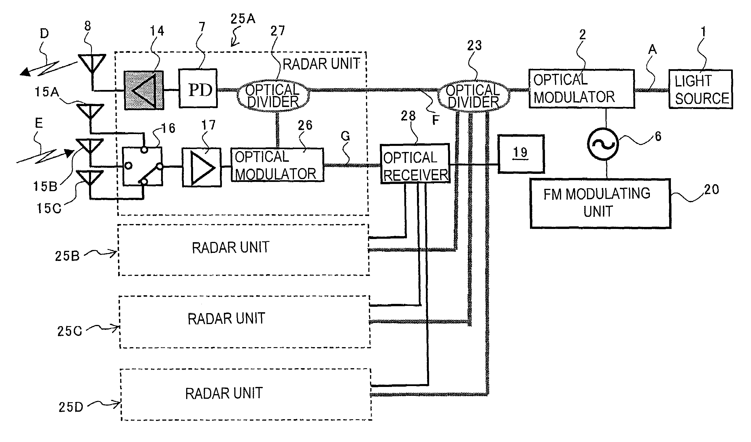
[0110]Then, a delta wave of the above radiation frequency was modulated to operate the optical modulator 2 according to the same method. It was thus proved that FMCW signal of a central frequency of 76 GHz was radiated. The signal was irradiated to a moving object from the transmitting antenna 8, and the reflected signal was received with the receiving antennas 15A, 15B and 15C.

[0111]The transmitted signal and received signals were mixed by the mixer 18 to draw the beat signal shown in FIG. 14, so that the distances and relative velocities could be detected. It was confirmed that the actual distance of 100 m and actual velocity of 50 km of the moving object were measured.

example 3

[0112]Radio signal radiation was performed according to the same procedure as the example 1. According to the present example, however, Ti-diffusion waveguides 5A, 5B and CPW electrodes 4A, 4B and 4C were formed on a substrate 3 of x-cut lithium niobate. The width of the central electrode 4B was made 50 μm. The gaps G of the central electrode 4B and the ground electrodes 4A and 4C, respectively, were made 15 μm, the electrode thickness was made 15 μm and the electrode length was made 40 mm.

[0113]The modulator substrate was adhered to a dummy plate fixed onto a surface plate with a thermoplastic resin for the thinning, so that the electrode face is oriented downwardly. The substrate was then subjected to horizontal polishing and polishing to a thickness of 6 μm. A plate-shaped reinforcing body of x-cut lithium niobate was adhered and fixed to the modulator substrate. The body was subjected to polishing at the end face to be connected to an optical fiber and cut into chips by dicing. ...


PUM

PropertyMeasurementUnit
gap widthaaaaaaaaaa
thicknessaaaaaaaaaa
thicknessaaaaaaaaaa

Abstract

The present invention provides a radio signal radiation system that alleviates the necessity of a highly specified pass band reception filter and a high performance / reliability amplifier. The radio signal radiation system includes an optical modulator; a light source for inputting an optical carrier wave into the optical modulator; a power source for applying a modulating signal having a frequency Fm on the optical modulator to superimpose a sideband wave onto the carrier wave, the modulating signal having an amplitude of N-times the drive voltage of the optical modulator; a light receiver to receive and convert the outgoing light into an electrical signal; and a radiating means for radiating a radio signal based on the electrical signal, wherein the sideband wave is superimposed at a position shifted by n×fm.

Description

[0001]This application is a continuation of Patent Cooperation Treaty application PCT / JP2005 / 013201 filed Jul. 11, 2005.FIELD OF THE INVENTION[0002]The present invention relates to radio signal radiation systems and radar systems.BACKGROUND OF THE INVENTION[0003]In Intelligent Transport Systems (ITS), it has been widely demanded a radar system utilizing radio wave such as an on-vehicle radar system. It has recently been developed, and partly commercialized, a radar system utilizing radio wave of 76 GHz band.[0004]An on-vehicle radar system is provided on the front side of a vehicle body so that it can measure the direction, distance and relative velocity of a car running ahead of the vehicle body to function as a sensor for preventing a car accident. It will be strongly demanded that an auto cruise control (ACC) system controls the speed of a vehicle and assures a safe distance between cars. It is thus required to detect obstacles on the sides of the vehicle, such as passing vehicle...

Claims


Application Information

Patent Timeline
Patent Type & Authority Patents(United States)
IPC IPC(8): G01S7/35G01S13/34G01S13/00G01S13/93G01S7/282G01S13/931G02F1/01G02F1/03H04B1/04
CPCG01S7/35G01S13/345H04B1/04H04B1/408G01S13/931G01S2013/9325H04B2001/0491H04B2210/006G01S2013/9321
Inventor KONDO, JUNGOMITOMI, OSAMUAOKI, KENJIYOSHINO, TAKASHIMATSUHIRO, KEIJI
Owner NGK INSULATORS LTD
Why Eureka
Try Eureka