Integrated LTCC mm-wave planar array antenna with low loss feeding network

a planar array antenna and low-loss technology, applied in the field of array antennas, can solve the problems of low element radiation efficiency, high surface wave loss, and less attractive conventional microstrip patch array antennas on multi-layer ceramic substrates. achieve the effect of high gain

Inactive Publication Date: 2008-11-04
THE CHINESE UNIVERSITY OF HONG KONG
View PDF7 Cites 7 Cited by
  • Summary
  • Abstract
  • Description
  • Claims
  • Application Information

AI Technical Summary

Benefits of technology

[0007]It is an object of the present invention to provide an array antenna working at mm-wave frequency band with high radiation efficiency and low loss from feeding network by using quasi-cavity-backed patch elements and a mixed feeding network configuration.
[0008]To accomplish the object of the present invention, a novel configuration of integrated LTCC array antenna working at mm-wave frequency band has been proposed by exploiting the flexibility of LTCC technology for three-dimensional integration. The antenna array uses quasi-cavity-backed patches as radiating elements. This configuration can be used in various integrated mm-wave antenna module. In order to reduce the loss from feeding network, a mixed configuration of feeding network is proposed and verified by experiment.

Problems solved by technology

However, operating at mm-wave frequencies, a conventional microstrip patch array antenna on multilayer ceramic substrate would be less attractive because of its low element radiation efficiency and the loss from feeding network, which are caused by the relative high dielectric constant of a ceramic substrate.
However, working with the high dielectric constant substrate, a thicker substrate will lead to a higher surface wave loss and consequently degrade the radiation efficiency.

Method used


Image

  • Integrated LTCC mm-wave planar array antenna with low loss feeding network
  • Integrated LTCC mm-wave planar array antenna with low loss feeding network
  • Integrated LTCC mm-wave planar array antenna with low loss feeding network

Examples


Embodiment Construction

[0022]The present invention and various advantages thereof will be described with reference to exemplary embodiments in conjunction with the drawings.

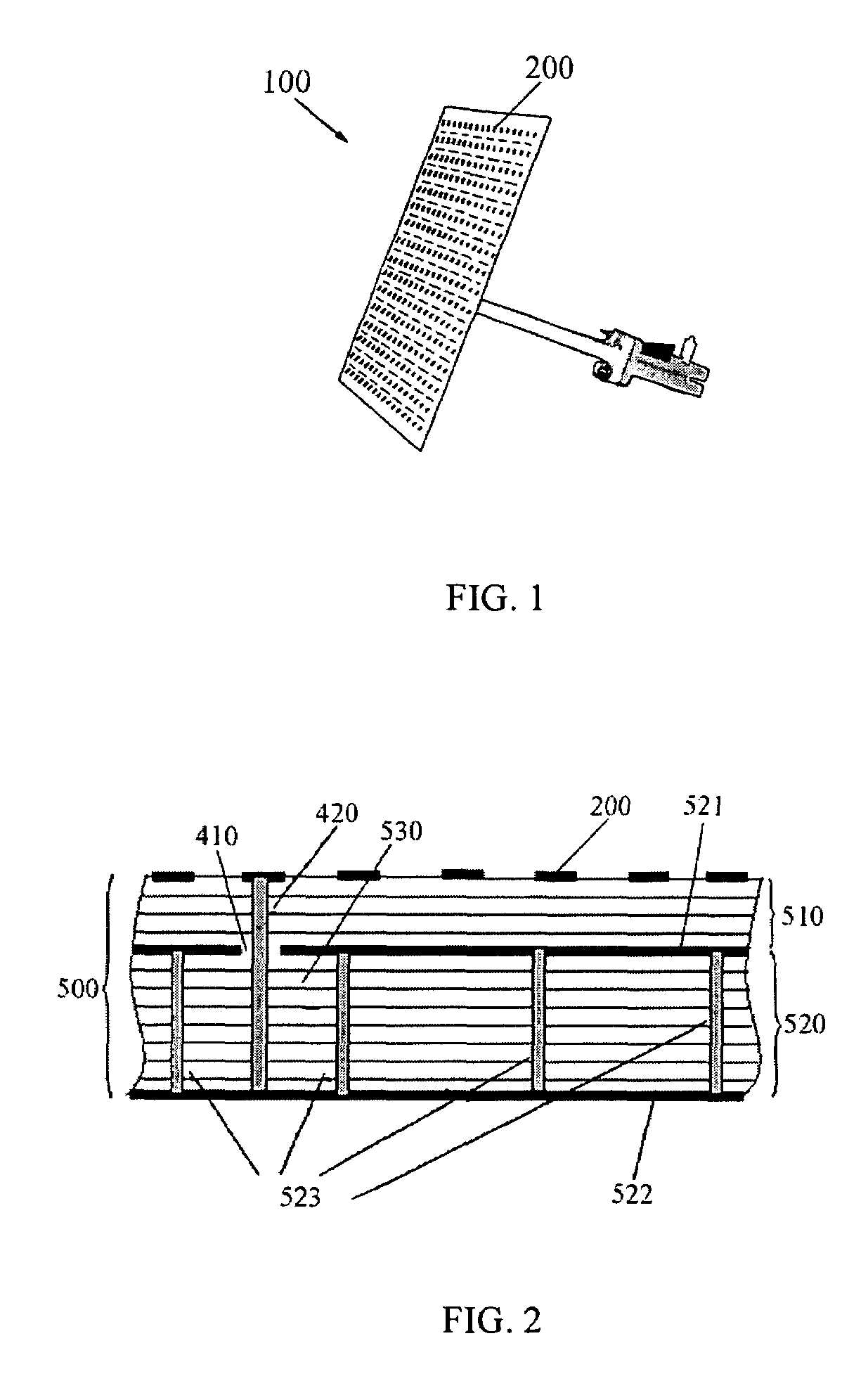
[0023]FIG. 1 shows an array antenna 100 of the present invention. According to the present embodiment, the array antenna 100 comprises 256 quasi-cavity-backed patch (QCBP) antennas 200 including 16 columns and 16 rows, and a multi-layered Low Temperature Co-fired Ceramic (LTCC) substrate 500.

[0024]As shown in FIG. 2, the LTCC substrate 500 of the array antenna 100 comprises a first substrate 510 which further comprises four low temperature co-fired ceramic layers, and a second substrate 520 which further comprises eight low temperature co-fired ceramic layers. The 256 patch antennas 200 are provided on a top surface 511 of the first substrate 510. A bottom ground plane 522 is stacked on the bottom of the second ceramic substrate 520.

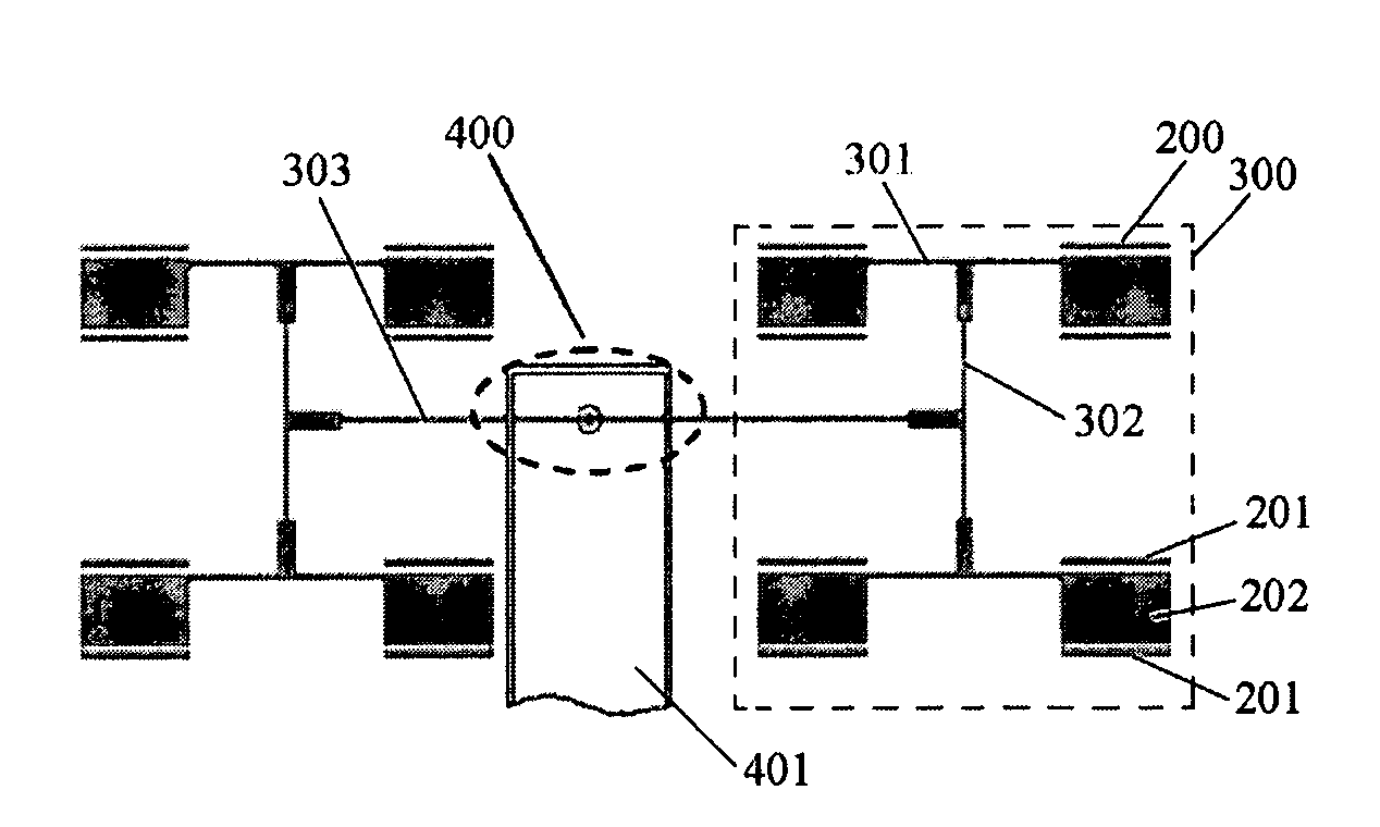
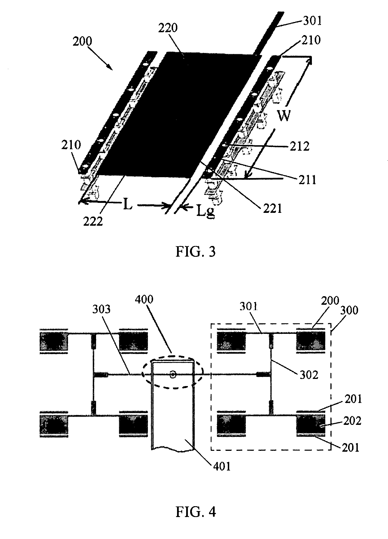
[0025]Referring to FIG. 3, each patch antenna 200 of the array antenna 100 comprises a radiating element...


PUM


Abstract

An array antenna comprises a first substrate comprising a first plurality of ceramic layers; a second substrate comprising a second plurality of ceramic layers; a bottom ground plane stacked on the bottom of the second ceramic substrate; a plurality of quasi-cavity-backed patch antennas mounted on a top surface the first substrate, each of the patch antennas including a radiating element and two grounded grid-like conductor walls; and a mixed feeding network coupled to each of the patch antennas. The array antenna working at mm-wave frequency band can provide high radiation efficiency and low loss from feeding network by using quasi-cavity-backed patch elements and a mixed feeding network configuration.

Description

[0001]This application claims the benefit of U.S. provisional patent application No. 60 / 663,139 filed Mar. 17, 2005 which is explicitly incorporated by reference in its entity.TECHNICAL FIELD OF THE INVENTION[0002]This invention relates to an array antenna, and more particularly to an integrated mm-wave planar array antenna based on a multilayer ceramic technology such as Low Temperature Co-fired Ceramic (LTCC) technology.BACKGROUND OF THE INVENTION[0003]With the increasing demands of commercial mm-wave application such as Collision Avoidance Radar and Local Multi-points Distribution System (LMDS), a multi-layered large-scale array antenna has attracted some attention due to its flexibility in manufacturing, the capability of passive integration, and the low production cost. One potential application is to build a microstrip patch array antenna in a multilayer ceramic substrate. However, operating at mm-wave frequencies, a conventional microstrip patch array antenna on multilayer ce...

Claims


Application Information

Patent Timeline
Patent Type & Authority Patents(United States)
IPC IPC(8): H01Q1/38
CPCH01Q21/0075H01Q21/065
Inventor WU, KE-LIHUANG, YONG
Owner THE CHINESE UNIVERSITY OF HONG KONG
Why Eureka
Try Eureka