
Conductive peptide nanofiber and method of manufacture of the same

a technology of conductive peptides and nanofibers, which is applied in the direction of peptide sources, peptide/protein ingredients, and therapeutics. it can solve the problems of risk of disulfide bonding between cys and nanofibers, difficult design for imparting desired properties, and inability to obtain nanofibers with desired properties. it is advantageous in terms of synthesis efficiency and synthesis time, and achieves the effect of improving the efficiency of synthesis and synthesis

Inactive Publication Date: 2008-11-11
KOBE UNIV +1
View PDF1 Cites 0 Cited by
  • Summary
  • Abstract
  • Description
  • Claims
  • Application Information

AI Technical Summary

Benefits of technology

"The present invention provides a conductive peptide nanofiber that can be easily obtained without using a giant protein and without inhibiting nanofiber formation. The nanofiber has a stable fiber-forming ability and can be further processed to impart desired properties. The conductive substance can be added to the peptide in a controlled manner, and the resulting nanofiber has a predictable structure. The use of a peptide with a nanofiber-forming ability and a short peptide sequence reduces the risk of byproduct formation and purification difficulties. The conductive peptide nanofiber can be used as a conductive material for various applications."

Problems solved by technology

Therefore, addition of functional molecules at a desired three-dimensional position may be difficult, thus resulting in difficulty in designing for the purpose of imparting a desired property.
In turn, to obtain nanofibers having a desired property is still difficult.
Furthermore, in proteins having Cys, there is a risk of formation of a disulfide bond between Cys unless the protein is especially kept in the solution in a reduced state.
As the number of the constituting amino acid residues is larger, the amount of byproduct having a molecular weight approximate to the intended peptide would be also greater, thereby causing difficulties in purification and separation.

Method used


Image

  • Conductive peptide nanofiber and method of manufacture of the same
  • Conductive peptide nanofiber and method of manufacture of the same
  • Conductive peptide nanofiber and method of manufacture of the same

Examples


examples

[0052]In this Example, the amino acid sequence of a peptide nanofiber to which a conductive function was imparted is Glu-Phe-Ile-Val-Ile-Phe-Lys (SEQ ID NO: 2), the abbreviation of which herein being EK7aa.

[0053](Experimental Method)

[0054]1. Synthesis of Peptide

[0055]Synthesis of peptide was conducted based on solid phase synthesis with a peptide synthesis system (Pioneer; Applied Biosystems). Support resin used in the solid phase synthesis was a PEG-PS resin (Applied Biosystems) to which: a 9-fluorenylmethoxycarbonyl (Fmoc) protecting group was added for protecting the Nα-amino group; a t-butoxycarbonyl (tBoc) protecting group was added for protecting the lysine residue side chain; and a t-butoxy (OtBu) protecting group was added for protecting the glutamic acid side chain. For coupling of the amino acid, an amino acid to which the protecting group was introduced (Peptide Institute, Inc.) was used, while N-[(dimethylamino)-1H-1,2,3-triazole[4,5-6]pyridin-1-ylmet hylene]-N-methylmet...


PUM

PropertyMeasurementUnit
diameteraaaaaaaaaa
diameteraaaaaaaaaa
temperatureaaaaaaaaaa

Abstract

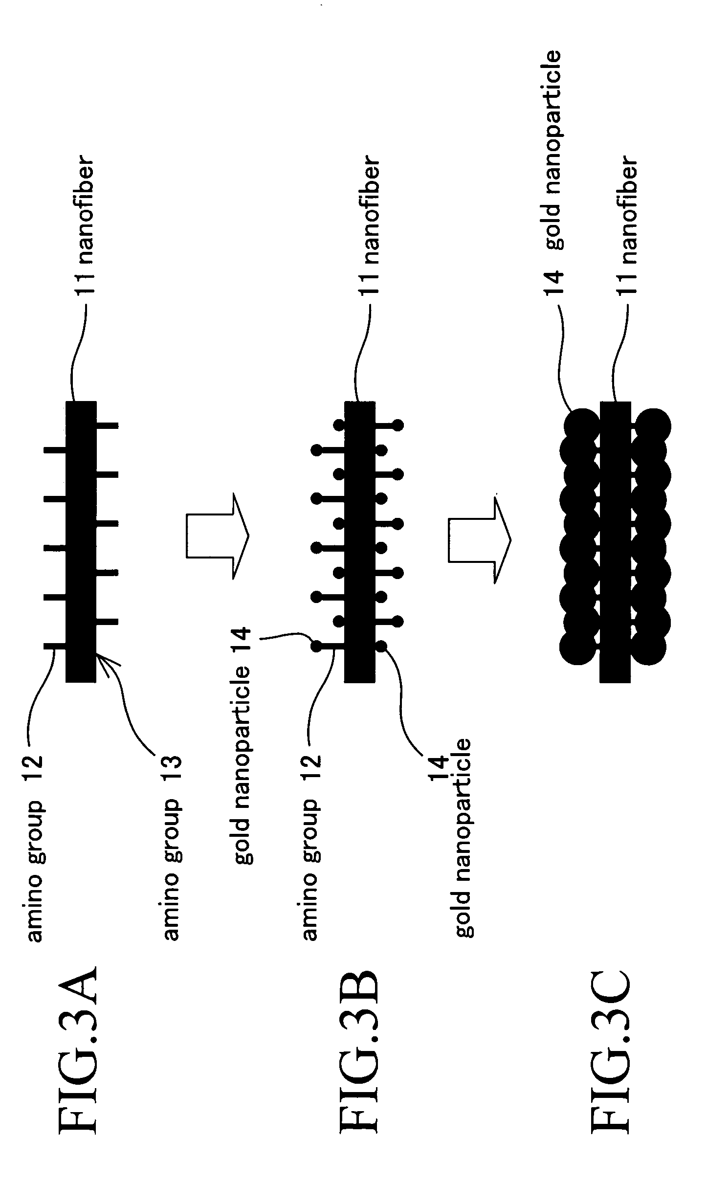
A peptide nanofiber having conductivity is provided. A conductive peptide nanofiber which includes a nanofiber formed through a manner of self-assembly of a peptide that has a nanofiber-forming ability and consists of an amino acid sequence of Xaa-Phe-Ile-Val-Ile-Phe-Xaa (SEQ ID NO: 1, wherein N-terminal Xaa is an arbitrary amino acid residue Xaa1; C-terminal Xaa is an arbitrary amino acid residue Xaa2; and Xaa1 and Xaa2 are an amino acid having an acidic side chain, an amino acid having a basic side chain, or an amino acid having a side chain with polarity according as acidity and basicity) or a derivative of the peptide and a conductive substance added thereto, the aforementioned conductive substance being added to an amino group of the peptide or the derivative.

Description

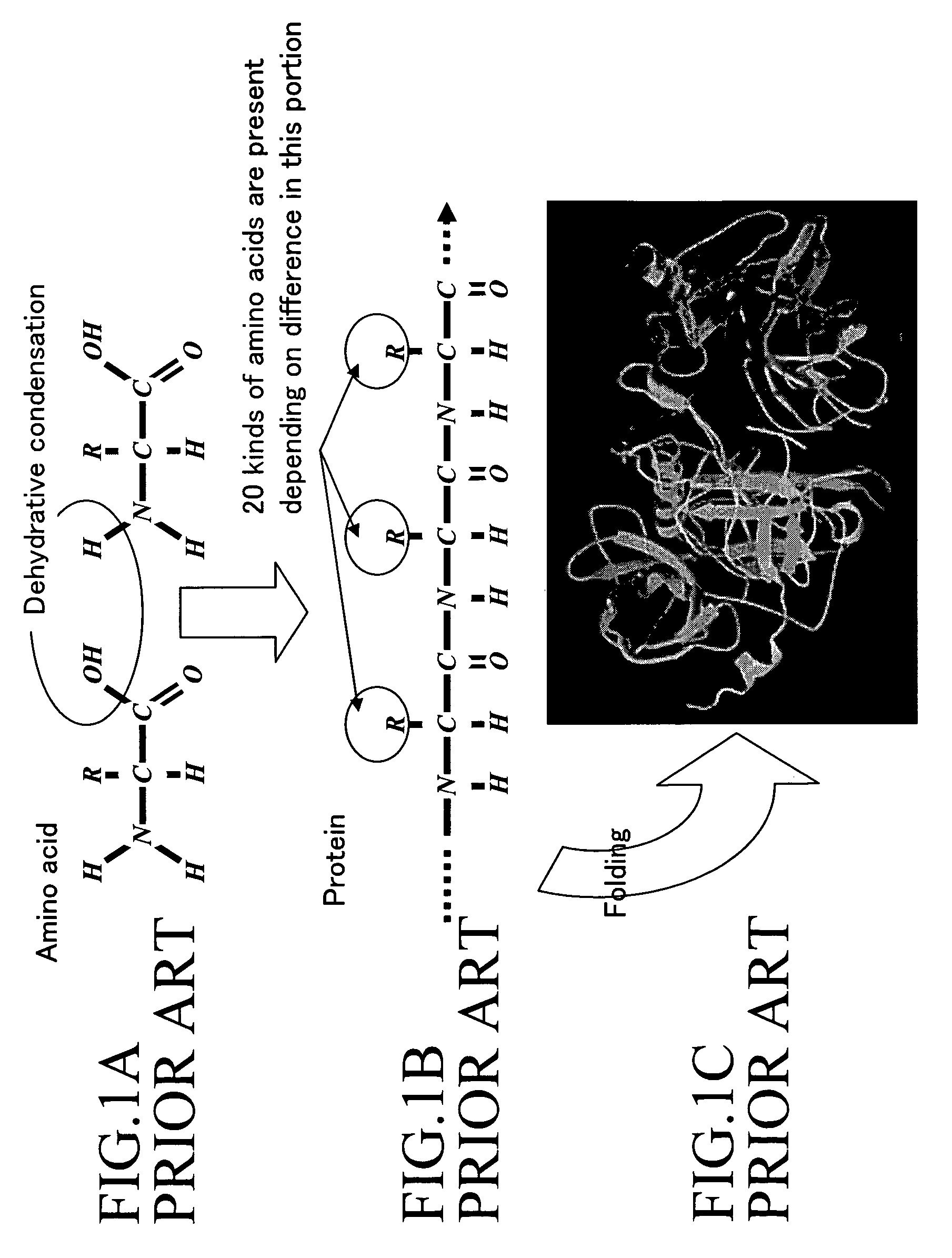
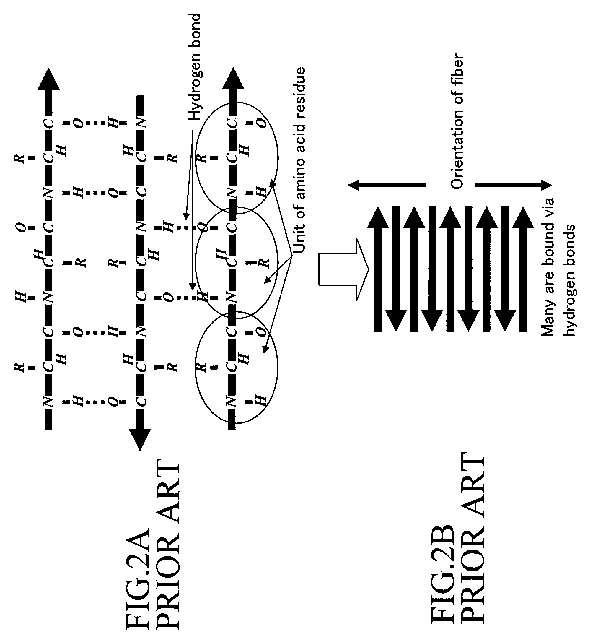
BACKGROUND OF THE INVENTION[0001]1. Field of the Invention[0002]The present invention relates to a peptide nanofiber having conductivity formed from a peptide that has a nanofiber-forming ability or a derivative of the peptide, and a method of manufacturing the same.[0003]2. Description of the Related Art[0004]Technology development for producing semiconductor elements and large-scale integrated circuits (LSI) using “top down” type approaches in which a large substance is subjected to miniaturization to give nanometer scale by cutting have been hitherto carried out extensively. However, such techniques have their limits, i.e., microstructures of 20 nm or less can not be produced. Thus, in recent years, investigations on construction of regular fine structures utilizing self-assembly of molecules have rapidly progressed. Representative examples of mimicking models for the “bottom up” type approach utilizing such self-assembly include cells of organisms, and investigations on developm...

Claims


Application Information

Patent Timeline
Patent Type & Authority Patents(United States)
IPC IPC(8): A61K38/00A61K38/04C07K2/00C07K5/00C07K7/00C07K4/00A61K51/00A01N37/18A61M36/14C07K14/00C07K16/00C07K17/00
CPCC07K7/06C07K14/001Y10S930/28Y10S977/705Y10S977/729
Inventor ONIZUKA, KENTAROTANAKA, SHUHEISUGIHARA, HIROKAZUTAMURA, ATSUO
Owner KOBE UNIV
Learn More