Magnetic element and method of manufacturing magnetic element

a technology of magnetic elements and manufacturing methods, which is applied in the manufacture of magnetic elements, transformers/inductance magnetic cores, cores/yokes, etc., can solve the problems of small possibility of reducing unstable various characteristics of magnetic elements, and reducing or limiting the performance and safety of magnetic elements in the environment. , to achieve the effect of stabilizing temperature characteristics and reducing the number of processes

Inactive Publication Date: 2008-11-11
SUMIDA CORP
View PDF3 Cites 4 Cited by
  • Summary
  • Abstract
  • Description
  • Claims
  • Application Information

AI Technical Summary

Benefits of technology

[0013]With this structure, since the temperature characteristics adjusting means is arranged between the core members opposing each other, end faces of the core members are both in close contact with the temperature characteristics adjusting means due to the existence of this temperature characteristics adjusting means. Accordingly, it is possible to prevent occurrence of a situation such that the butted core members contact each other only partly and thus a non-contact part occupies the most part. Thus, it is possible to realize stabilization of temperature characteristics in various characteristics of the magnetic element. Also, by ensuring the stabilization of temperature characteristics in various characteristics of the magnetic element, dispersion of temperature characteristics in various characteristics of a product manufactured with the same specification is improved, and thus the quality of this product can be improved. Further, by limiting the thickness dimension of the temperature characteristics adjusting means according to the present invention to 3 μm to 30 μm, the temperature characteristics adjusting means with high precision can be obtained easily at low cost without using precise cutting, grinding, chemical polishing method, and the like. Also, a state that magnetic saturation would not easily occur can be created while suppressing decrease in magnetic permeability.
[0021]According to the present invention, it is possible to stabilize temperature characteristics in various characteristics of the magnetic element.

Problems solved by technology

A large factor of reducing or limiting performance and safety of magnetic elements is temperature variation (also called temperature load) in environment where they are used.
For example, when a magnetic element is used under a condition with relatively small temperature load such as a room temperature, a possibility of reducing performance and safety of the magnetic element is small.
However, when electronic equipment having the magnetic element is used under a high temperature condition, or when the magnetic element itself is mounted on a power supply circuit or the like involving relatively large current, various characteristics of the magnetic element may often become unstable.
In such cases, in the magnetic element, there arises a possibility of causing thermal runaway or malfunction inside a circuit or equipment.
However, when the end faces being butted are observed microscopically, numerous dents and projections resulting from scratching by grinding, baking the surface of magnetic substance, or the like exist on the end faces.
Therefore, the magnetic element has a problem such that when it is subjected to temperature load, and then expansion, contraction and the like occur in the magnetic cores, a change occurs in percentage of contact around minute dents and projections, thereby worsening a change due to a temperature in various characteristics (temperature characteristics of various characteristics).
However, the above means require high precision in cutting equipment and grinding equipment, and also the time required in a series of processes largely increases.
Therefore, in aspects of cost, process time, and the like, it is not easy to adopt these techniques for mass production of the magnetic element.
Thus, in the magnetic element disclosed in Patent document 1, productivity is quite low.
This requires to pay attention to directivity when mounting inductance parts, and moreover, if an input direction of current is reversed, directions of the magnetic flux and the magnetic force become the same, which causes a problem of adversely affecting the temperature characteristics.

Method used


Image

  • Magnetic element and method of manufacturing magnetic element
  • Magnetic element and method of manufacturing magnetic element
  • Magnetic element and method of manufacturing magnetic element

Examples


first embodiment

[0047]Note that the magnetic element 40 has a solid part 42 having a microscopic structure that is different from that of the solid part 16 in the

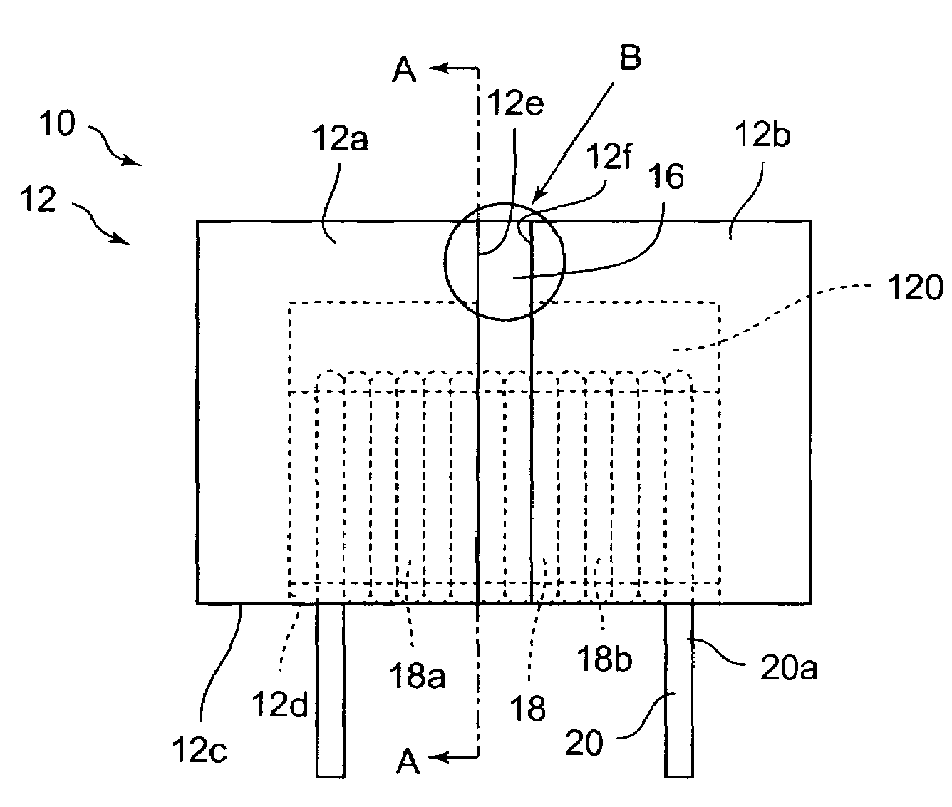
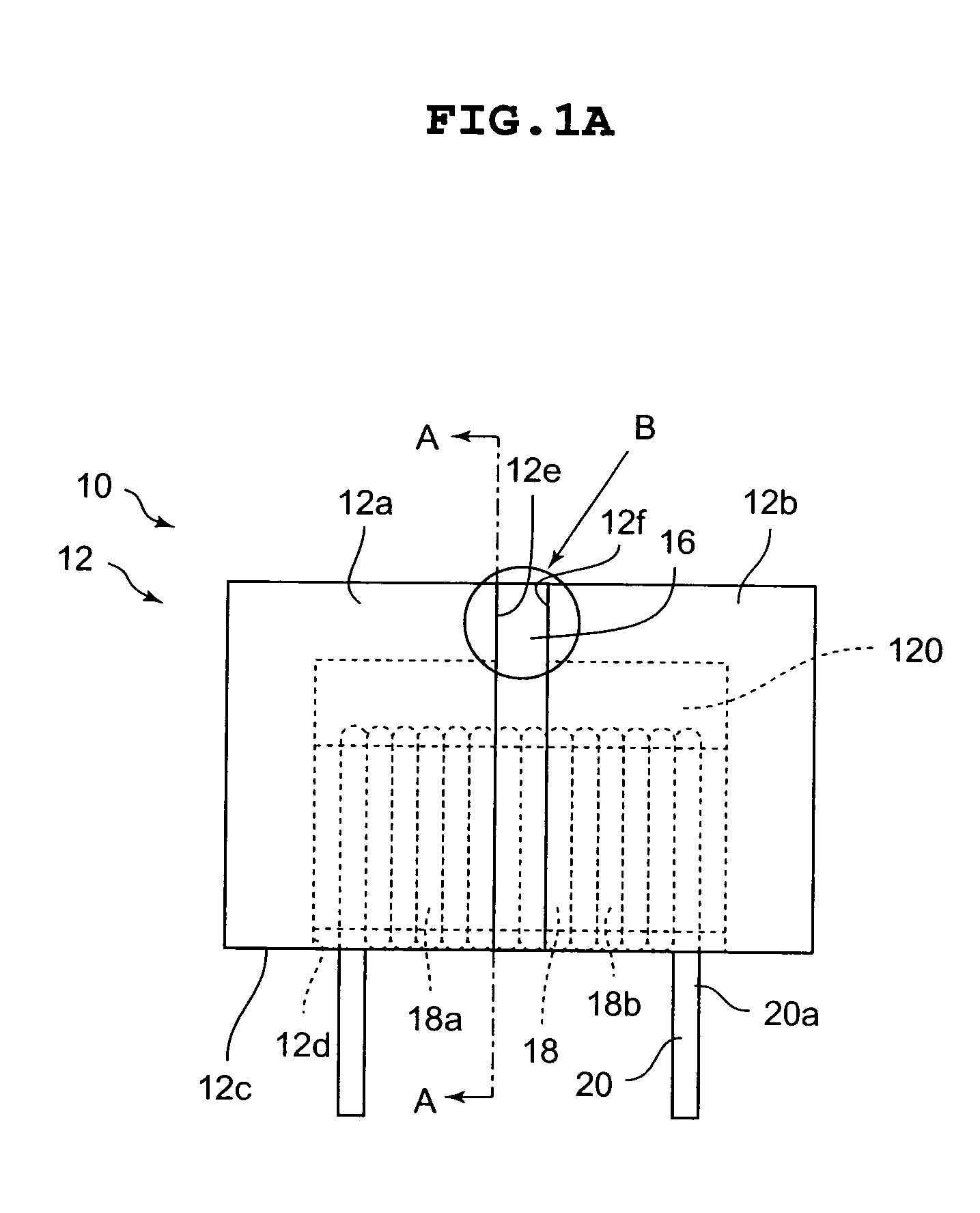
[0048]In the magnetic element 40, similarly to the first embodiment, the solid part 42 having a thickness dimension ranging from 3 μm to 30 μm is provided between the end face 12e on the one end side of the EP core 12a and the end face 12f on the other end side of the EP core 12b. Here, in the second embodiment, the solid part 42 is made by directly depositing powder with a dimension range of 3 μm to 30 μm on the end face 12e on the one end side of the EP core 12a and the end face 12f on the other end side of the EP core 12f. In other words, in a state that the EP core 12a and the EP core 12b are butted with each other, the solid part 42 is, as shown in FIG. 3, in a state of having a large amount of powder 42a deposited directly on the end face 12e and the end face 12f.

[0049]Further, when the magnetic core body 12 is formed by butting the...

fourth embodiment

[0089]Further, in the fourth embodiment, values of the ultrasonic frequency, the processing time for ultrasonic fusing and the pressing force are 19.15 kHz, 0.2 seconds to 0.3 seconds, and 0.1 MPa to 0.2 MPa, respectively. However, they are not limited to these values, where the ultrasonic frequency may range from 17 Hz to 21 Hz, the processing time for ultrasonic fusing may be 0.1 seconds to 0.5 seconds, and the pressing force may range from 0.05 MPa to 0.4 MPa, to thereby combine these respective values.

[0090]The magnetic element and the method of manufacturing the magnetic element according to the present invention may be used in various types of electronic parts such as inductances, transformers, filters, and the like.


PUM

PropertyMeasurementUnit
thicknessaaaaaaaaaa
heightaaaaaaaaaa
particle diameteraaaaaaaaaa

Abstract

A problem to be solved is to stabilize temperature characteristics in various characteristics of a magnetic element. A magnetic element has a coil formed by winding a conductor, EP cores constituted of a magnetic material and passing magnetic flux generated in the coil, a solid part provided between EP cores opposing each other among the EP cores, and having a ceramics material or a resin material, in which the solid part is in contact with opposing faces of the respective opposing EP cores, and the solid part is provided with a thickness dimension ranging from 3 μm to 30 μm.

Description

CROSS-REFERENCE TO RELATED APPLICATION[0001]This Application claims priority to Japanese Application No. 2005-026102 filed Feb. 2, 2005, the entire disclosure of which is hereby incorporated by reference.BACKGROUND OF THE INVENTION[0002]1. Field of the Invention[0003]The present invention relates to a magnetic element used for electronic parts such as inductors, noise filters, transformers, and the like and a method of manufacturing the magnetic element.[0004]2. Description of the Related Art[0005]In recent years, regarding electronic equipment and electronic parts, demands for increasing performance, reducing size, improving safety and the like are becoming stronger. Magnetic elements in particular are often used in important application for operating electronic equipment, such as transmitting a signal, rectifying power supply, and the like. Therefore, increasing performance, reducing size, as well as ensuring more safety are demanded.[0006]A large factor of reducing or limiting pe...

Claims


Application Information

Patent Timeline
Patent Type & Authority Patents(United States)
IPC IPC(8): H01F17/06
CPCH01F3/14H01F17/045H01F41/0206H01F27/008H01F27/24
Inventor URANO, YUICHIROMEGURO, FUMIHITOKAWAHATA, YOSHIO
Owner SUMIDA CORP
Why Eureka
Try Eureka