Electrophotograph developing roller and image forming device using the same

a developing roller and developing roller technology, applied in the direction of electrographic process equipment, instruments, optics, etc., can solve the problems of increased low mechanical rigidity of aluminum alloy, and increase in material cost and processing cost, and achieve satisfactory outside diameter deflection accuracy, suitable for color image formation, and good mechanical rigidity.

Inactive Publication Date: 2008-11-11
FUJI ELECTRIC CO LTD
View PDF17 Cites 9 Cited by
  • Summary
  • Abstract
  • Description
  • Claims
  • Application Information

AI Technical Summary

Benefits of technology

[0039]According to the invention, it is possible to provide an electrophotographic developing roller for non-magnetic one-component non-contact development which is satisfactory in air tightness and electrical conductivity in the fit section of the metal flange to be press fitted in both end sections of the cylindrical metal base body, satisfactory in outside diameter deflection accuracy and suitable for color image formation. Also, according to the invention, by improving a material of the cylindrical metal base body of the (developing roller, it is possible to provide a developing roller which is inexpensive and excellent in mechanical rigidity, surface processability and corrosion resistance and satisfactory in a prescribed dimensional accuracy and which is especially suitable as a developing roller which is used in a developing unit which is used in a color electrophotographic device of a non-magnetic one-component non-contact development system.

Problems solved by technology

In order to meet the foregoing dimensional accuracy, since the aluminum tube stock is poor in mechanical rigidity because it is a hard-to-cut material, a special processing method for reducing a processing strain (return of residual stress) due to cutting or polishing processing for revealing shape accuracy (straightness and coaxiality) is necessary, and in order to resist the processing strain, the wall thickness of the tube stock must be further thickened, resulting in increases in material costs and processing costs, whereby the price becomes high.
However, since an aluminum alloy is low in mechanical rigidity, in such a roughing treatment, the wall thickness must be made thick in order to resist a processing strain to be applied on the surface of the base body.
In addition, in maintaining a frictional electrification performance with a developer, a material having high abrasion resistance is demanded because the aluminum alloy is relatively low in hardness.
Moreover, in the electroless formation of a nickel plating layer, an aluminum alloy is a material having a base oxidation-reduction potential, and nickel is hardly deposited directly thereon, resulting in a problem in adhesion.
Accordingly, since stable film formation is difficult, selection of a material which does not require a special pre-treatment is demanded.

Method used


Image

  • Electrophotograph developing roller and image forming device using the same
  • Electrophotograph developing roller and image forming device using the same
  • Electrophotograph developing roller and image forming device using the same

Examples


experimental examples 1 to 8

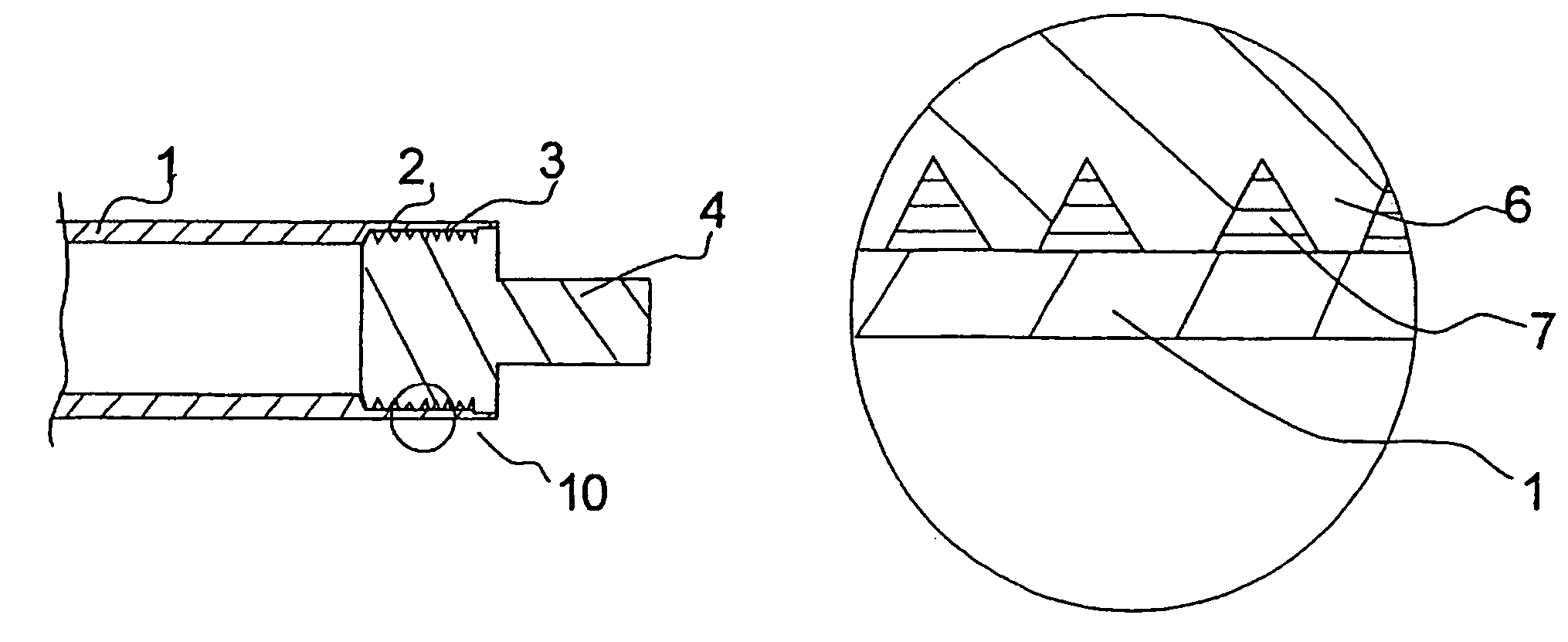
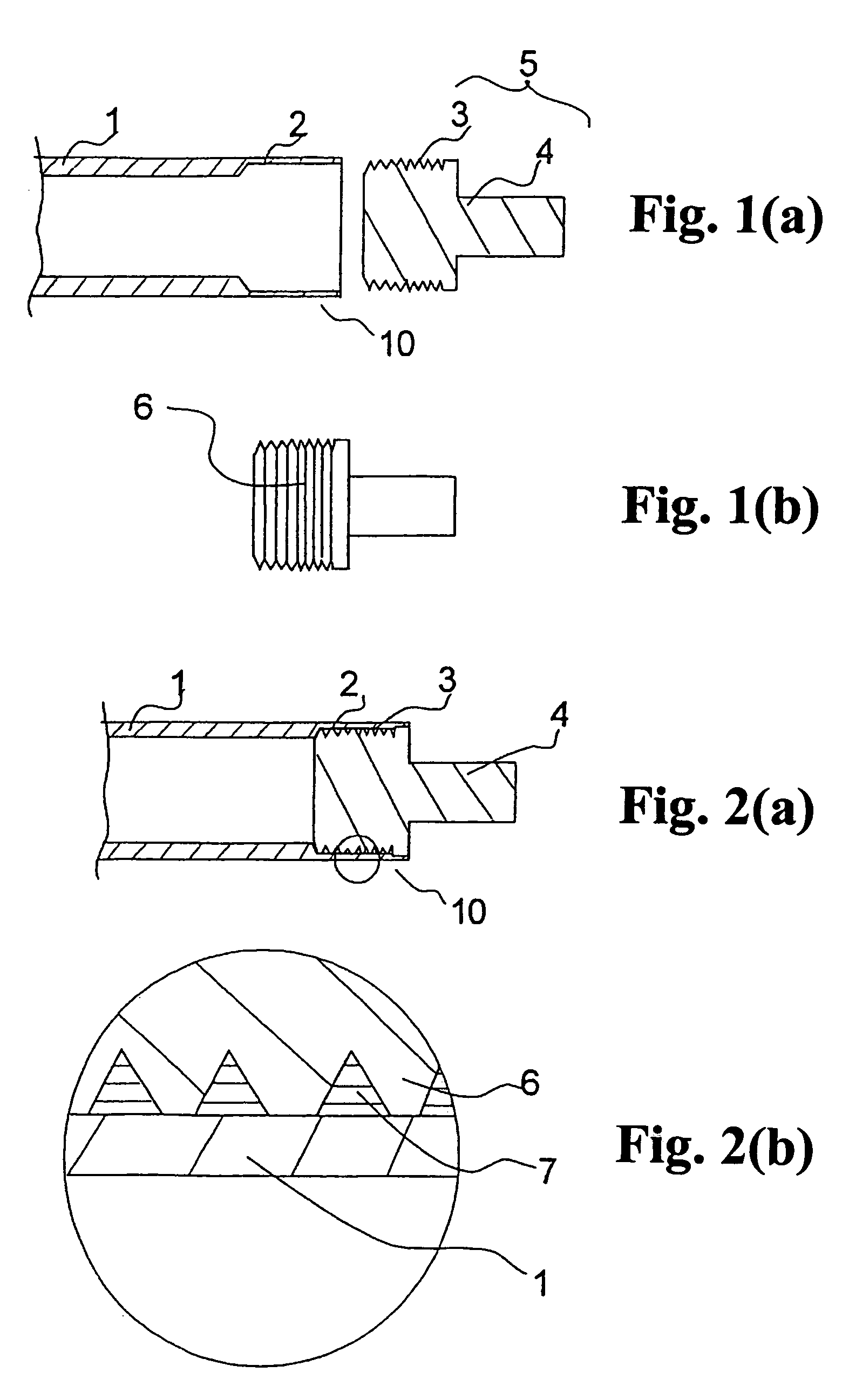
[0076]As the cylindrical metal base body 1 shown in the foregoing FIG. 1(a), a carbon steel tube (STKM11A) having a length of 350 mm, an outside diameter of 18.00 mm and an inside diameter of 16.00 mm is used, and a countersunk section having an inside diameter of 16.12 mm is formed in the both end sections thereof. As the metal flange 5 in the same drawing, a round bar of a free cutting steel (SUM24) is processed by cutting or other means into a shape having an outside diameter of the larger diameter section 3 of 16.17 mm and an outside diameter of the smaller diameter section 4 of 10.00 mm. In that case, an interference between the inner surface of the foregoing countersunk section and the outside diameter of the foregoing fit section is about 50 μm (since there are precisely tolerable dimensional errors in both the outside diameter of the fit section and the inside diameter of the countersunk section, the term “about” is used). In addition, a streak section 6 having a maximum sur...

experimental example 1

[0078]A developing roller was prepared under the same condition as in that described above, except that as the streaking condition, the maximum surface roughness Ry and the pitch distance were changed to 22 μm and 115 μm, respectively.

experimental example 2

[0079]A developing roller was prepared under the same condition as in that described above, except that as the streaking condition, the maximum surface roughness Ry and the pitch distance were changed to 25 μm and 148 μm, respectively.


PUM


Abstract

An electrophotographic developing roller in which air tightness and electrical conductivity in a fit section between a cylindrical metal base body and a metal flange are satisfactory and outside diameter deflection accuracy is satisfactory; and an electrophotographic developing roller which is relatively inexpensive, excellent in mechanical rigidity, surface processability and plating film formation (corrosion resistance) and capable of being satisfied with a prescribed dimensional accuracy are provided. The electrophotographic developing roller is a developing roller having a cylindrical metal base body and a metal flange. The metal flange has a larger diameter section to be fitted in the opening end inner surface of the cylindrical metal base body and a smaller diameter section serving as a central shaft body coaxial with the cylindrical metal base body. The fit section surface of the larger diameter section before being press fitted has an uneven shape such that a maximum surface roughness Ry due to a circumferential groove formed by cutting processing is from 25 μm to 70 μm.

Description

TECHNICAL FIELD[0001]The present invention relates to an electrophotographic developing roller which is used in image forming devices by an electrophotographic system such as printers, copiers, and facsimiles. In particular, the invention relates to an electrophotographic developing roller to be used in a non-magnetic one-component non-contact development system and to an image forming device using the same.BACKGROUND ART[0002]An image forming device by an electrophotographic system performs repeated image formation by successively executing respective steps of charging, exposure, development, transfer, and cleaning by a charger, an exposing unit, a developing unit, a transfer unit, a cleaning unit, and the like which are disposed in the vicinity on the outer peripheral surface of a photoreceptor for forming an electrostatic latent image, thereby outputting a printed image. Recently, there is also present a cleaning-less system for simultaneously carrying out a cleaning step in a de...

Claims


Application Information

Patent Timeline
Patent Type & Authority Patents(United States)
IPC IPC(8): G03G15/08
CPCG03G15/0818G03G15/06G03G15/08
Inventor TSUBOTA, TOSHIOMATSUZAWA, SHINJI
Owner FUJI ELECTRIC CO LTD
Why Eureka
Try Eureka