Feedforward control processes for variable output hydrogen generators

a technology of variable output and control process, which is applied in the direction of combustible gas purification/modification, fluid pressure control, combustible gas production, etc., can solve the problems of inability to quickly change the hydrogen supply rate of the fuel cell, limited use of fuel cells, and inability to solve. , to achieve the effect of slowing down and reducing carbon monoxide emissions

Inactive Publication Date: 2008-11-18
HYRADIX INC
View PDF22 Cites 6 Cited by
  • Summary
  • Abstract
  • Description
  • Claims
  • Application Information

AI Technical Summary

Benefits of technology

[0017]The processes of this invention pertain to operating hydrogen generators, especially hydrogen generators integrated with fuel cells, having a variable hydrogen production output rate such that the operation of the hydrogen generators exhibits enhanced efficiency and stability and maintains hydrogen product purity during transitions among hydrogen production rates. In an aspect of the processes of this invention, feedforward, rather than feedback, is used to define the control of the hydrogen generator.
[0022]The externally-provided materials comprise fuel (hydrocarbon-containing feed), oxygen-containing gas, and water. Not only can the control processes of this aspect of the invention avoid instability and / or undue time lags characteristic of control systems requiring feedback, but also the control processes can enhance efficiency and reduce time in effecting changes in hydrogen production rate while maintaining desired hydrogen product purity. This is achieved because the rates of feed of the externally-provided raw materials are predetermined to effect the change, or transition, to the sought hydrogen production rate.

Problems solved by technology

Unfortunately, the use of fuel cells has been limited especially where a rapid change in electricity demand is required such as in residential applications.
The problem is that the rate of hydrogen supply to the fuel cell must rapidly change in order to accommodate varying electrical loads.
However, such a solution is impractical, especially for residential use, due to difficulties and risks associated with such storage.
Moreover, hydrogen storage equipment adds to the size and cost thereby reducing the attractiveness of a fuel cell for residential use.
Batteries, especially of the volume required to meet the needs of residential units, also add to the cost and size of the fuel cell system.
Moreover, batteries have a limited life and must be replaced.
While the size and cost of a super capacitor may be attractive, the disadvantage is the limited storage capacity.
Although technology exists for the generation of hydrogen by reforming fuels, the implemented production processes are not able to quickly change the rate of hydrogen generation so as to be useful in a residential fuel cell application.
On-site hydrogen supply for fuel cells used in smaller mobile and stationary facilities, including residential-scale facilities, poses substantial problems even without the added complexities of operating at varying production rates.
The challenge associated with providing smaller scale hydrogen generators is readily apparent from the number of unit operations required to convert fuel to hydrogen suitable for use in a fuel cell.
The severity of the problem in changing hydrogen generation rates is exacerbated in that the range of operation of residential units needs to be quite wide, often the turndown ratio must be at least 5:1.
The difficulties in providing a hydrogen generator for use with fuel cells is further exacerbated because carbon monoxide is a poison to certain fuel cells such as PEM (polymer electrolyte membrane or proton exchange membrane) fuel cells.
Any upset in the operation of the water gas-shift reactor can result in an increase in carbon monoxide that must be removed in downstream treatment of the hydrogen-containing gas.
While redundant capacity for carbon monoxide removal (e.g., a selective oxidation) may be used in downstream operations to handle spikes in carbon monoxide production, such an approach will incur a penalty in process efficiency and product purity, as well as compactness and cost of the system.
The two primary disadvantages are slow transient response and instability during transitions, especially rapid transitions.
Slow response and instability can result in not only loss of efficiency but also can adversely affect the hydrogen product purity and, in some instances, can result in damage to catalyst and equipment.

Method used


Image

  • Feedforward control processes for variable output hydrogen generators
  • Feedforward control processes for variable output hydrogen generators
  • Feedforward control processes for variable output hydrogen generators

Examples


Embodiment Construction

Overview of Hydrogen Generators

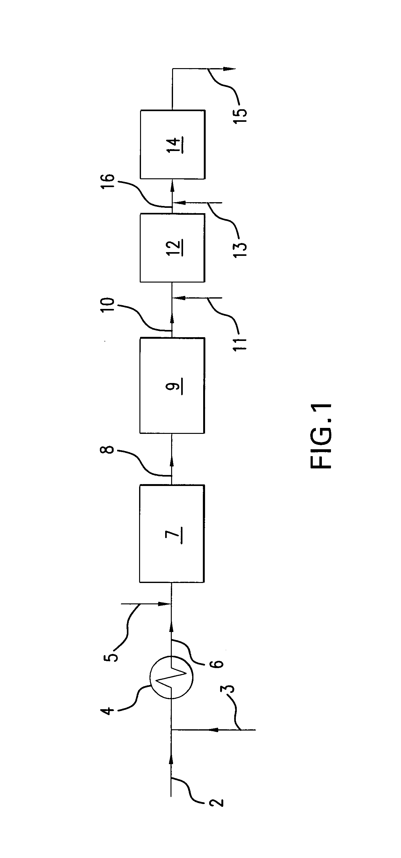
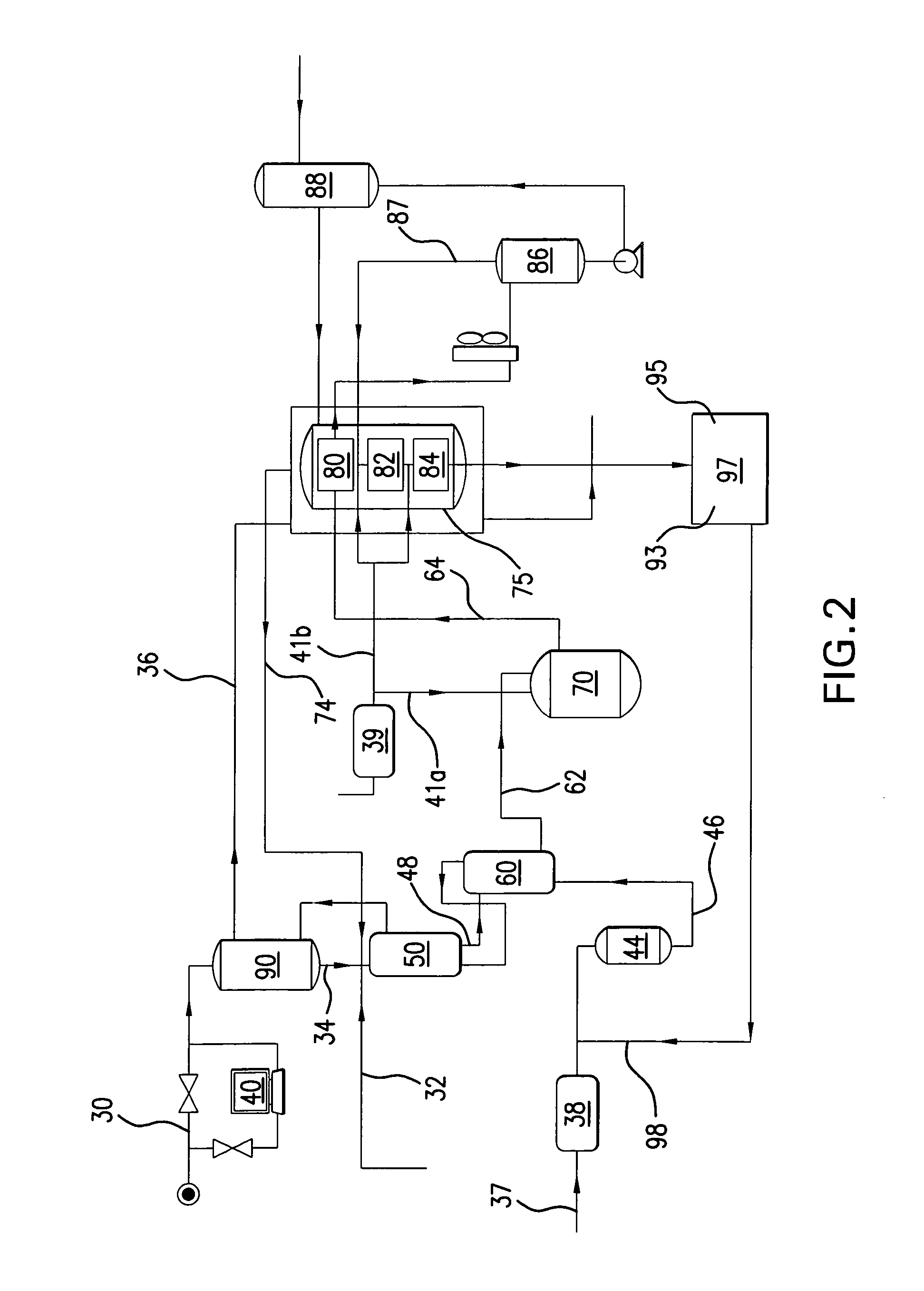
[0039]In the processes of this invention a fuel (hydrocarbon-containing feed) is subjected to a chemical reaction, reforming, to produce hydrogen. Reforming is typically an endothermic, catalytic reaction conducted at elevated temperatures. The generation of hydrogen, for instance, for feed to a fuel cell will also involve the conversion of carbon monoxide produced in the reforming reaction to carbon dioxide. The conversion may be a water gas shift reaction whereby water and carbon monoxide are reacted to produce additional hydrogen and carbon dioxide. Another carbon monoxide conversion process is a preferential, or selective, oxidation reaction through which selectively carbon monoxide is oxidized in the presence of free oxygen to carbon dioxide. As is known in the art, the hydrogen generation process may include various operations for treating the fuel, such as desulfurization, and for preparing the hydrogen product for use in a fuel cell such as dew...


PUM

PropertyMeasurementUnit
temperaturesaaaaaaaaaa
pressuresaaaaaaaaaa
temperaturesaaaaaaaaaa

Abstract

Hydrogen generators and integrated hydrogen generator / fuel cells systems are operated by determining the condition of the hydrogen generator and the condition of the fuel to the hydrogen generator for selection of predetermined flow rates for each of the externally-provided raw materials. The processes of the invention can provide rapid transitions between hydrogen production rates while enabling enhanced efficiency and stability during transient operations.

Description

CROSS-REFERENCE TO RELATED APPLICATION[0001]This application is a Continuation-In-Part of application Ser. No. 10 / 209,486 filed Jul. 30, 2002 now abandoned, the contents of which are hereby incorporated by reference.FIELD OF THE INVENTION[0002]This invention pertains to processes for operating variable output hydrogen generators and integrated hydrogen generator / fuel cell systems. The processes include control processes that enable rapid transitions to reflect changes in output demandBACKGROUND OF THE INVENTION[0003]Fuel cells convert hydrogen and oxygen to water, releasing energy as usable electricity without employing combustion as an intermediate step. Unfortunately, the use of fuel cells has been limited especially where a rapid change in electricity demand is required such as in residential applications. The problem is that the rate of hydrogen supply to the fuel cell must rapidly change in order to accommodate varying electrical loads.[0004]One could use a reservoir of hydroge...

Claims


Application Information

Patent Timeline
Patent Type & Authority Patents(United States)
IPC IPC(8): C10J1/28C01B3/00C01B3/32G05B17/00G05D16/00G05D7/00H01M8/00H01M8/04H01M8/18B01J8/00B01J19/00C01B3/48
CPCB01J8/001C01B3/48B01J19/0006Y02E60/324B01J2219/00006B01J2219/00164B01J2219/00191C01B2203/00C01B2203/0233C01B2203/0244C01B2203/0283C01B2203/0288C01B2203/044C01B2203/047C01B2203/0495C01B2203/066C01B2203/0811C01B2203/0844C01B2203/0877C01B2203/0883C01B2203/1052C01B2203/1082C01B2203/1241C01B2203/127C01B2203/1276C01B2203/1288C01B2203/1294C01B2203/142C01B2203/143C01B2203/146C01B2203/147C01B2203/1604C01B2203/1614C01B2203/1661C01B2203/1685C01B2203/169C01B2203/1695C01B2203/80C01B2203/82Y02E60/50Y02E60/32
Inventor RUSSELL, BRADLEY P.HARNESS, JOHN R.BLOMMEL, PAUL G.SIOUI, DANIEL R.ABDO, SUHEIL F.VANDEN BUSSCHE, KURT M.SANGER, ROBERT J.
Owner HYRADIX INC
Why Eureka
Try Eureka