
Information processing unit

a technology of information processing and information processing unit, which is applied in the direction of unauthorized memory use protection, memory adressing/allocation/relocation, instruments, etc., can solve the problems of large electric power consumption of the gate circuit and the decryption of the contents of date processing performed on the ic card chip, so as to reduce the relevance

Inactive Publication Date: 2008-11-18
RENESAS ELECTRONICS CORP
View PDF11 Cites 11 Cited by
  • Summary
  • Abstract
  • Description
  • Claims
  • Application Information

AI Technical Summary

Benefits of technology

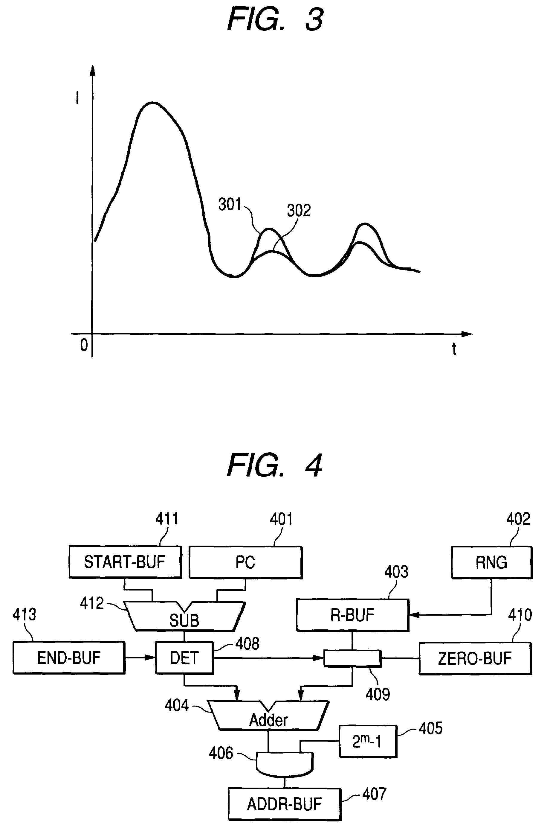
[0051]As clearly understood from the description of the above basic operation, the difference in control method causes waveforms of the power consumption to differ from each other. Judging from the difference in power consumption waveform, it is possible to identify which control method is being applied. If the control method for controlling a signal line is identified, it is possible to observe the influence of a bit value of the encryption key by changing data to be processed for a fixed encryption key to observe a change in power consumption in response to it. Moreover, a possibility of being able to predict an encryption key arises as a result of analyzing a waveform of the power consumption. Although information about a processing method, which is a target of the analysis, is required to determine a specific analysis method for analyzing the power consumption, it is possible to easily acquire information about an encryption system because encryption algorithm is opened to the public and is standardized, which are results of modern cryptography.
[0064]The present invention has an effect of making it difficult to predict a state inside a microcomputer by analyzing the power consumption, to read out data by probing a bus line, and to falsifying transmitted data. As a result, it is possible to improve the tolerance to an attack on encryption including the power analysis and the difference failure analysis.

Problems solved by technology

In particular, because a signal line has the large wire capacity, the gate circuit consumes the large electric power due to its charge and discharge when a data value of a bus changes from 1 to 0 or 0 to 1.
If such power consumption is observed, there is a possibility that contents of date processing performed in the IC card chip will be decrypted.

Method used


Image

  • Information processing unit
  • Information processing unit
  • Information processing unit

Examples


first embodiment

[0185]In this embodiment, placement of a data transform device at the time of storing data in a memory device from a CPU will be described.

[0186]Here, the data transform device is a device that performs nonlinear transformation of data. Data transform devices usually have a function of changing bit expression itself of data. There is another case where a data transform device has a function of changing bit expression itself of data and also has an order transform function of transforming the correspondence between a bit number of data and a number of a bus. Changing of bit expression means that the hamming weight of an image (D) by transformation F of a certain data D, the number of which is at least one, is different from that of D. The transformation of order means that all D are transformed so that the hamming weight of F (D) always agrees with that of D. The transformation of data is in general a union of a case where the bit expression is changed and a case where the order is c...

second embodiment

[0190]An embodiment shown in FIG. 15 is an example in which a data transform device is extended, and further untraceability of data is achieved by performing addition of key data R and data expansion before performing inverse calculation INV, prior to data transformation processing in the data transform function. Here, the above addition means logical addition D′=D xor R. After completing the above processing, the data-bit length is extended by concatenation of the data D′ with R, and thereby an input into the inverse calculation INV, which is a data transform function, is obtained. The concatenation is parallel connection of the data D′ with R. This means that data, the bit length of which is equivalent to the sum of the bit length of both data, is obtained. This is expressed as D′|R. Data D0 output from a CPU 1501 is inputted into a data transform device 1502. The data transform device 1502 further comprises a key addition function 1503, a data expansion function 1504, and an inve...

third embodiment

[0196]This embodiment shows an example of how a data transform device is configured. A basic data transform device has only a data transform function 1601. As shown in FIG. 16, the data transform device receives data D, and then performs data transformation before outputting data D′. However, a configuration as illustrated in FIG. 17 may also be used. More specifically, a data transform device 1701 further receives data R as an input. The data R is treated as a key, and accordingly the key is stored in a key data storing register 1702. The key is added to data D in a key addition function 1703. A data expansion function 1704 then expands the data by combining the result of the addition and the key R. After that, the expanded data is inputted into a data transform function 1705, which outputs the transformed data as D′. FIG. 18 is a configuration example in which data R can be read out. If key data which is concatenated with data changes as a result of an attack, it becomes impossibl...


PUM


Abstract

An object of the present invention is to a provide tamper resistant information processing unit that is used as an IC card with a high level of security.To achieve the above-mentioned object, the information unit of the present invention comprises: a program container part for storing a program; a memory for storing data; an arithmetic unit for performing specified processing according to the program; a data bus for connecting the memory to the arithmetic unit; and a transform function for transforming a logical address and a physical address of the memory, said logical address being used for arithmetic operation by the arithmetic unit, said physical address being set at random corresponding to the logical address at each arithmetic operation or every time the information processing unit is started up.

Description

CLAIM OF PRIORITY[0001]The present application claims priority from Japanese application JP 2003-387524, filed on Nov. 18, 2003, and JP 2004-027550 filed on Feb. 4, 2004, the content of which is hereby incorporated by reference into this application.BACKGROUND OF THE INVENTION[0002]1. Field of the Invention[0003]The present invention relates to a tamper resistant information processing unit with a high level of security, and more particularly to a technique that is extremely effective if the technique is applied to IC cards, and the like.[0004]The present invention relates to a tamper resistant information processing unit capable of preventing processing information from being read and analyzed by power analysis or hardware probing in the information processing unit. Further, the present invention relates to a fault-detectable tamper resistant information processing unit that can detect a change in data and falsification of data caused by an attack at the time of writing / reading the...

Claims


Application Information

Patent Timeline
Patent Type & Authority Patents(United States)
IPC IPC(8): H04L9/00G06F12/00G06F12/02G06F12/04G06F12/14G06K19/073G07F7/10
CPCG06F12/1408H04L9/003H04L9/004H04L2209/127
Inventor KAMINAGA, MASAHIROWATANABE, TAKASHIENDO, TAKASHI
Owner RENESAS ELECTRONICS CORP
Learn More