Piezoelectric cantilever sensors

a technology of piezoelectric and cantilever sensors, applied in the field of sensors, can solve the problems of not being able to measure the change in mass, many of these techniques are not direct, nor quantitative, and many of them are also quite slow

Active Publication Date: 2008-12-02
DREXEL UNIV
View PDF19 Cites 58 Cited by
  • Summary
  • Abstract
  • Description
  • Claims
  • Application Information

AI Technical Summary

Benefits of technology

[0016]In a first aspect, the present invention relates to an apparatus for sensing mass having a non-piezoelectric layer, and a piezoelectric layer bonded to the non-piezoelec

Problems solved by technology

Most of these techniques are neither direct, nor quantitative.
Many of these techniques are also quite slow.
In addition, most of the aforementioned techniques do not lend themselves to measurement of changes in mass, which may provide a convenient way to measure a variety of different parameters.
In addition, the PZT vibration driver adds to the weight and complexity of the sensor.
Further, the external actuator can only be located at the base of the micro-cantilever, which greatly limits its effectiveness in driving the cantilever's vibration.
The optical means of detection also limits how small the micro-cantilever can be fabricated, and therefore limits the mass detection sensitivity.
Also, detecting the adsorption-induced stress in this manner offers no information about the amount of target antigen adsorbed on the cantilever.
Moreover, immersing silicon-based micro-cantilevers in water reduces the resonance intensity by an order of magnitude, reducing the Q factor, defined as the ratio of the resonance peak frequency relative to the resonance peak width at half peak height, to about one, thus making it impractical to use silicon-based micro-cantilevers for in-water detection.
The main reason that such silicon-based micro-cantilevers do not exhibit sufficiently high r

Method used


Image

  • Piezoelectric cantilever sensors
  • Piezoelectric cantilever sensors
  • Piezoelectric cantilever sensors

Examples


example 1

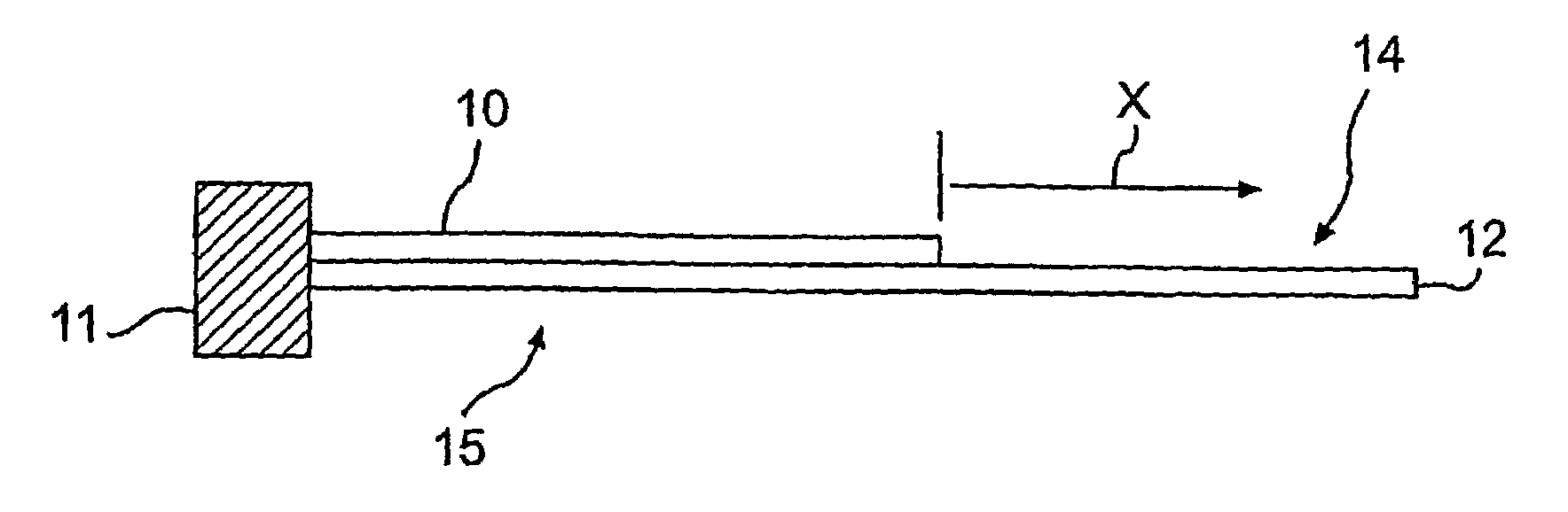
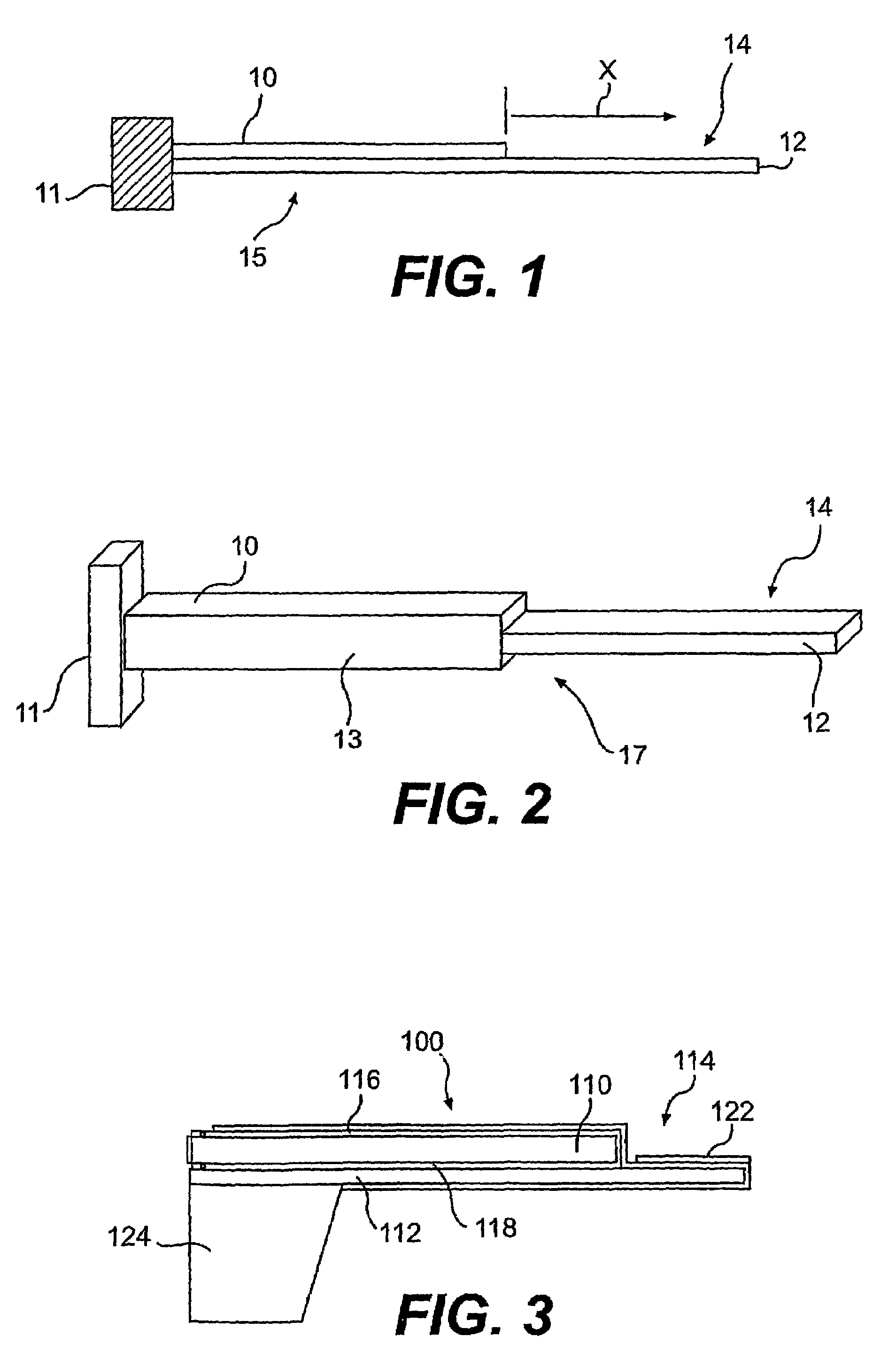
[0056]FIGS. 4-8f show various graphs that demonstrate the performance of PECS 15, and the effects of variations in the length of non-piezoelectric tip 14. PECS 15 detects mass changes by electrically monitoring resonance frequency shifts in flexural modes. The measured resonance frequencies range from 500 kHz to 1500 kHz, or from 1 kHz to 1000 kHz.

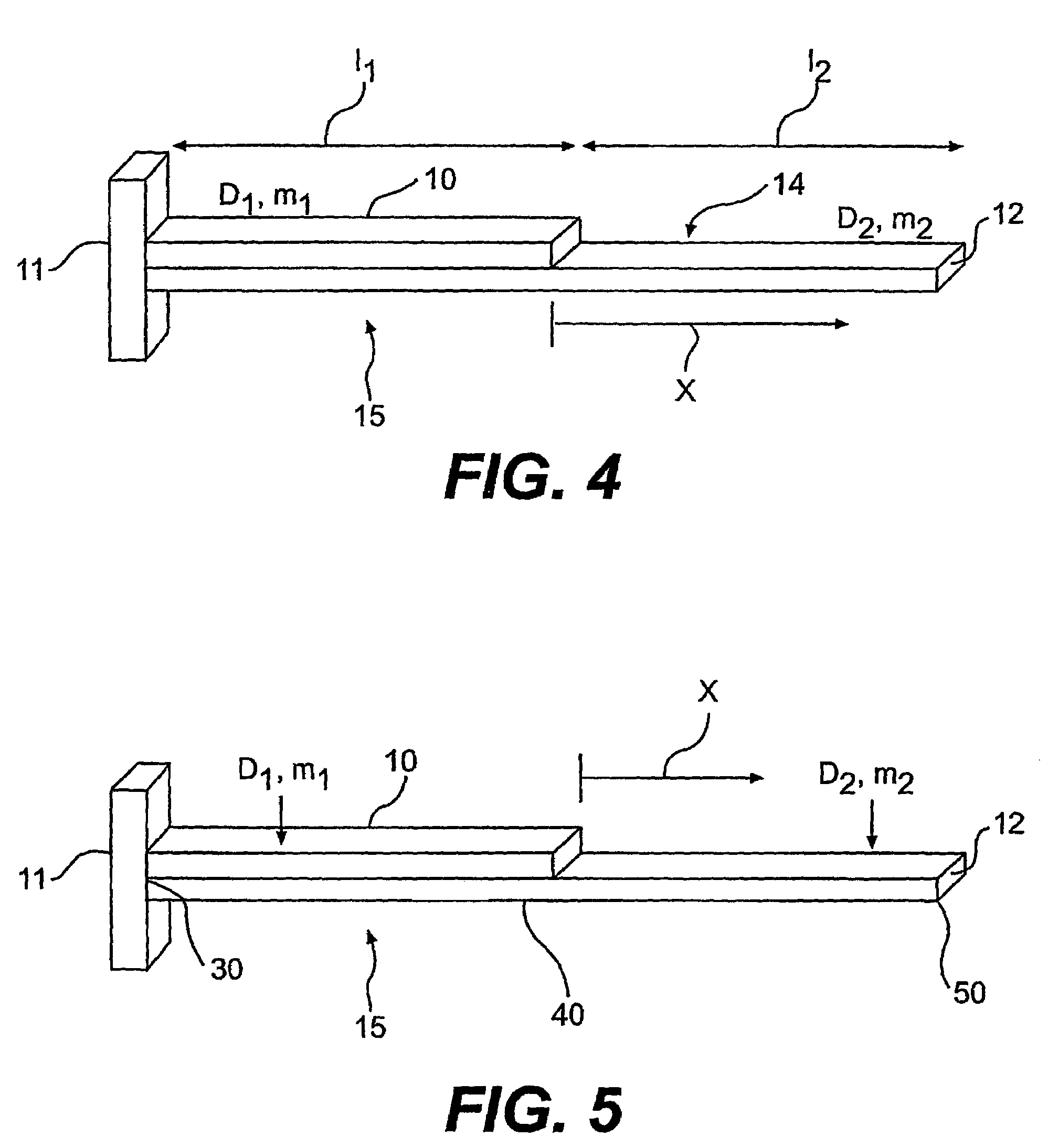
[0057]FIG. 4 shows a diagram of PECS 15 illustrating the parameters used in determining the geometry of PECS 15. The equation

[0058]Di⁢ⅆ4⁢hi⁡(x,t)ⅆx4+mi⁢ⅆ2⁢hi⁡(x,t)ⅆt2=0,i=1,⁢or⁢⁢2

governs the waveform for of PECS 15. The equation:

h1(x)=C11 sin(k1x)+C12 cos(k1x)+C13 sin h(k1x)+C14 cos h(k1x)

governs that portion of PECS 15 that extends for length l1 and contains both piezoelectric layer 10 and non-piezoelectric layer 12, while the equation:

h2(x)=C21 sin(k2x)+C22 cos(k2x)+C23 sin h(k2x)+C24 cos h(k2x)

governs that portion of non-piezoelectric layer 12 that begins at the end of l1 and extends the length of l2.

[0059]FIG. 5 shows the equations go...

example 2

[0076]This example shows the behavior of PECS 15 in three viscous solutions labeled as samples 1-3 in FIG. 9, as well as in air and water. This example demonstrates that the viscosity of the fluid in which PECS 15 is immersed, does not dramatically affect the resonance frequency. Therefore, PECS 15 will be useful for detection in viscous solutions. Furthermore, the ability to predict the behavior of the PECS 15 in various viscosities based upon the known geometry of PECS 15 permits the use of PECS 15 to measure the viscosity of a fluid. The viscosity of the three samples was measured by a rheometer. The viscosity of water and the three samples are, shown below in Table 1.

[0077]

TABLE 1Viscosity(cp)Δf (Hz)Q valueΔf / fair(%)Water114017.510.1Sample 124918011.613Sample 29952307.417Sample 337002805.620.3

[0078]Q=f / δf, with f representing the resonance frequency, and δf representing the width of the resonance peak at half the peak height. A higher Q value indicates a better signal intensity....


PUM


Abstract

A piezoelectric cantilever with a non-piezoelectric, or piezoelectric tip useful as mass and viscosity sensors. The change in the cantilever mass can be accurately quantified by monitoring a resonance frequency shift of the cantilever. For bio-detection, antibodies or other specific receptors of target antigens may be immobilized on the cantilever surface, preferably on the non-piezoelectric tip. For chemical detection, high surface-area selective absorbent materials are coated on the cantilever tip. Binding of the target antigens or analytes to the cantilever surface increases the cantilever mass. Detection of target antigens or analytes is achieved by monitoring the cantilever's resonance frequency and determining the resonance frequency shift that is due to the mass of the adsorbed target antigens on the cantilever surface. The use of a piezoelectric unimorph cantilever allows both electrical actuation and electrical sensing. Incorporating a non-piezoelectric tip (14) enhances the sensitivity of the sensor. In addition, the piezoelectric cantilever can withstand damping in highly viscous liquids and can be used as a viscosity sensor in wide viscosity range.

Description

STATEMENT OF GOVERNMENT INTEREST[0001]This invention was reduced to practice with Government support under Grant No. NAG2-1475 awarded by NASA, Grant No. R01 EB00720-01 awarded by NIH and Grant No. R-82960401 awarded by the EPA; the Government is therefore entitled to certain rights to this invention.BACKGROUND OF THE INVENTION[0002]1. Field of the Invention[0003]The invention relates to the field of sensors. In particular the invention relates to methods and apparatus for sensing biological and chemical species, as well as the measurement of viscosity.[0004]2. Description of the Related Technology[0005]Most of the current work done with biosensing technologies relies on fluorescence, lasers, fiber-optics-based methods, quartz crystal microbalance technology, electrochemical enzyme immunoassays, and binding to metal particles. Most of these techniques are neither direct, nor quantitative. Many of these techniques are also quite slow. In addition, most of the aforementioned technique...

Claims


Application Information

Patent Timeline
IPC IPC(8): G01N5/04G01N25/08G01NG01N1/00G01N29/02G01N29/036
CPCG01N5/02G01N29/022G01N29/036G01N2291/0255G01N2291/0256G01N2291/02818G01N2291/0422G01N2291/0426G01N2291/0427
Inventor SHIH, WAN Y.SHIH, WEI-HENGSHEN, ZUYAN
Owner DREXEL UNIV
Why Eureka
Try Eureka